page 39
Reference Manual
Networked PIP Series
• Reference measures both the impedance-vs.-frequency and frequency response of a
known good component. All other tests are compared to these results until a new reference
is created.
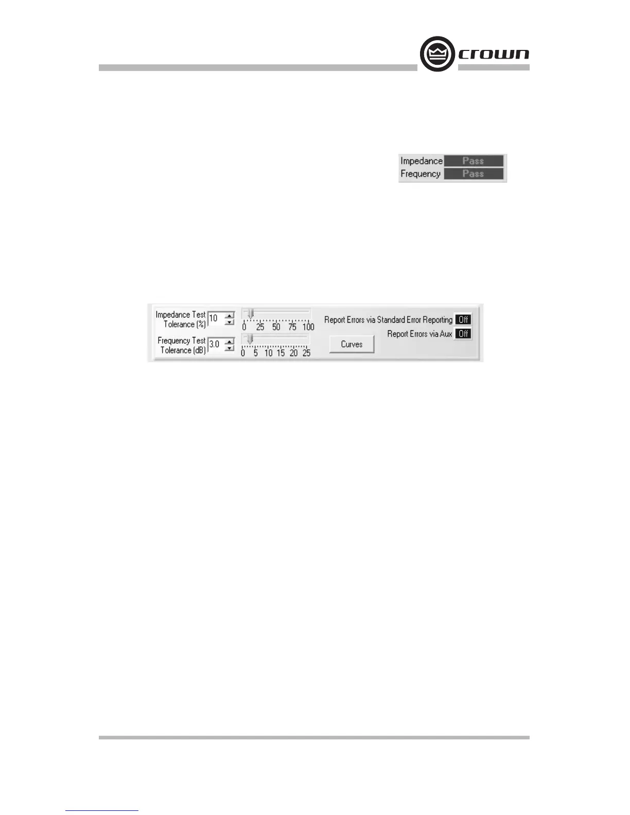
Impedance and Frequency Pass/Fail Indicators
These show whether the channel passed or failed the selected test.
Start/Stop Frequencies
These are the lowest and highest frequencies of the displayed curve. You can set these fre-
quencies either with the drop-down menus or with sliders on the frequency scale at the bot-
tom.
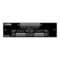
Tolerance Section of the SLM Tab
These controls allow you to set tolerances for impedance and frequency tests.
Impedance Tolerance (1% to 100%, one per channel)
Use the Impedance Tolerance control to set the percentage of difference by which an imped-
ance test may vary from the reference and still be considered "passing." Tests conducted
where the impedance is measured at a percentage outside this tolerance at any point along
the frequency range will be considered "failed" for purposes of the impedance test. Use
either the drop-down menu or the slider.
Frequency Tolerance (1 dB to 25 dB, one per channel)
Use the Frequency Tolerance control to set the difference in dB by which a frequency test
may vary from the reference and still be considered "passing." Tests conducted where the
frequency is measured at a dB level outside of this tolerance at any point along the fre-
quency range will be considered "failed" for purposes of the frequency test. Use either the
drop-down menu or the slider.
Report Errors
Report Errors via Standard Error Reporting: If this button is set to the on position, the
results of a test are reported in the standard error reporting windows.
Report Errors via Aux: If this button is set to the on position, the results of a test are
reported via the Aux Out port of the USP3 or USP3/CN. The Aux Out port will be set high if
all tests have a Pass result. It will be set low if any of the tests fail.
Conducting a Test
Once tests are set up, you may initiate a test by clicking on the Start button located at the
top of the Control Panel. This will cause a swept sine wave to be generated through each
channel at the frequencies and levels defined. While a test is in progress, the Testing LED
will blink. Once a test is completed, the "Pass/Fail" indicators will be updated accordingly.