XLS Series Power Amplifi ers
Operation Manual
page 6
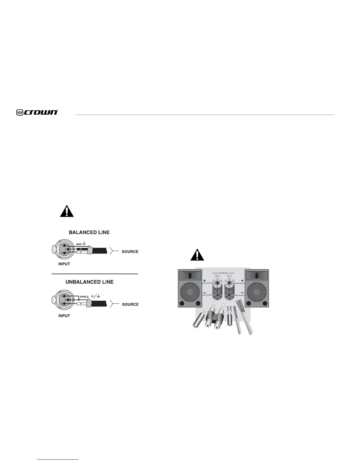
Figure 3.4. Input Connector Wiring
3 Setup
3.5 Choose Input Wire
and Connectors
Crown recommends using pre-built or profes-
sionally wired, balanced line (two-conductor
plus shield), 22-24 gauge cables and connec-
tors. You should use 3-pin male XLR cable
ends at the amplifi er inputs. Unbalanced line
may also be used but may result in noise over
long cable runs.
Note: Male XLR signal links are also provided
on the amplifi er to allow daisy-chaining of the
audio signal.
Refer to Figure 3.4 for correct XLR connector
pin assignments.
NOTE: Custom wiring should only be
performed by qualifi ed personnel.
Figure 3.5. Output Connector Wiring
3.6 Choose Output Wire
and Connectors
Crown recommends using pre-built or pro-
fessionally wired, high-quality, two- or four-
conductor, heavy gauge speaker wire and
connectors. You may use banana plugs, spade
lugs or bare wire for your output connectors
(see Figure 3.5). To prevent the possibility
of short-circuits, wrap or otherwise insulate
exposed loudspeaker cable connectors.
Using the guidelines below, select the appro-
priate size of wire based on the distance from
amplifi er to speaker.
Distance Wire Size
up to 25 ft. 16 gauge
26-40 ft. 14 gauge
41-60 ft. 12 gauge
61-100 ft. 10 gauge
101-150 ft. 8 gauge
151-250 ft. 6 gauge
CAUTION: Never use shielded cable for
output wiring.
 Loading...