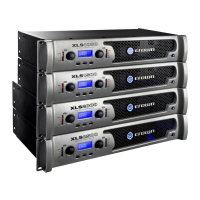
XLS Series Power Amplifiers
page 7
Operation Manual
2.4 Choose Input Wire
and Connectors
Crown recommends using pre-built or professionally wired bal-
anced line (two-conductor plus shield), 22-24 gauge cables and
connectors. You should use 3-pin male XLR cable ends at the
amplifier inputs. Unbalanced line may also be used but may
result in noise over long cable runs.
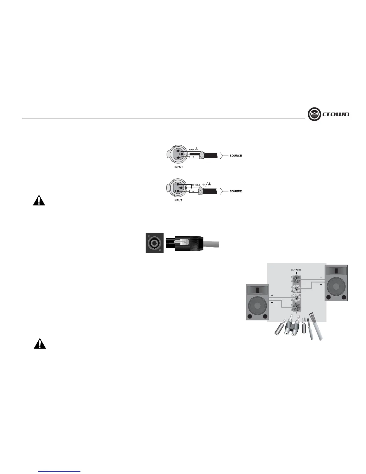
Figure 2.3 shows connector pin assignments for balanced wiring,
and Figure 2.4 shows connector pin assignments for unbalanced
wiring.
NOTE: Custom wiring should only be performed by
qualified personnel.
Figure 2.3
Balanced Input
Connector Wiring
Figure 2.4
Unbalanced Input
Connector Wiring
2 Setup
2.5 Choose Output Wire and Connectors
Crown recommends using pre-built or professionally wired, high-
quality, two-conductor, heavy gauge speaker wire and connectors.
You may use 2-pole or 4-pole Speakon
®
connectors (Figure 2.5 )
or banana plugs, spade lugs, or bare wire for your output connec-
tors (Figure 2.6). To prevent the possibility of short-circuits, wrap
or otherwise insulate exposed loudspeaker cable connectors.
Note: Binding post outputs on European models come
with safety plugs installed to prevent European power-
cord plugs from being inserted. The top & bottom entry
positions for these connectors should therefore be used
with European models.
Using the guidelines below, select the appropriate size of wire
based on the distance from amplifier to speaker.
Distance Wire Size
up to 25 ft. 16 AWG
26-40 ft. 14 AWG
41-60 ft. 12 AWG
61-100 ft. 10 AWG
101-150 ft. 8 AWG
151-250 ft. 6 AWG
CAUTION: Never use shielded cable for output wiring.
Figure 2.6
5-Way Binding Post Connections
Figure 2.5
Left: One of Two Speakon
®
Output Connectors
on Back Panel
Right: Speakon
®
Cable Connector
 Loading...