XLS Series Power Amplifiers
page 8
Operation Manual
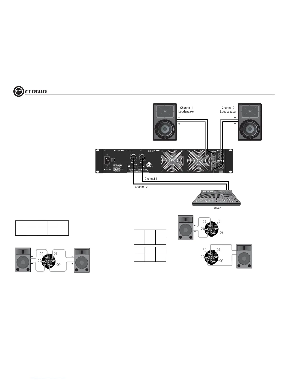
2.6 Wire Your System
2.6.1 Stereo Mode
Typical input and output wiring is shown in
Figure 2.7
INPUTS: Connect input wiring for both channels.
OUTPUTS: Maintain proper polarity (+/–) on output connectors.
Connect Channel 1 loudspeaker’s positive (+) lead to Channel 1
positive (red) terminal of amp; repeat for negative (–). Repeat
Channel 2 wiring as for Channel 1.
Figure 2.7 shows how to wire stereo speakers to the 5-way binding
posts.
To wire stereo speakers to the Speakon
®
connectors, use one of
these methods:
Method 1 (Table 1 and Figure 2.8): Wire one Speakon cable con-
nector to two speakers. Insert the Speakon cable connector into the
amplifier’s top Speakon connector.
Method 2 (Table 2 and Figure 2.9): Plug the Channel 1 speaker
into the Channel 1 (top) Speakon connector, and plug the Channel
2 speaker into the Channel 2 (bottom) Speakon connector.
2 Setup
Figure 2.7
System Wiring,
Stereo Mode
Using the 5-way
Binding Posts
PIN 1+ 1– 2+ 2–
CH 1+ 1– 2+ 2–
Stereo Wiring Method 1: Use Top Speakon Only
Table 1
PIN 1+ 1–
CH 2+ 2–
PIN 1+ 1–
CH 1+ 1–
Stereo Wiring Method 2: Use Both Speakons
Figure 2.9 Stereo Wiring Method 2:
Connect Each Speaker to a Different Speakon Connector
Figure 2.8 Stereo Wiring Method 1:
Wire Two Speakers to the Top Speakon
Connector
Table 2
Channel 1
Loudspeaker
Channel 2
Loudspeaker
Top Speakon
(Channel 1)
Bottom
Speakon
(Channel 2)
 Loading...