Tech Note
Crown Technical Support
PO Box 1000 Elkhart IN 46515
Ph 800-342-6939/574-294-8200
Fax 574-294-8301
Page 1 of 3
Issue Date: March 26, 2007
Ref. No: Tech Note #184 Rev. A
Subject: Discharge resistor modification procedure for all XTi, DSi, and CDi models.
Applicability: All XTi, CDi, and DSi amplifier manufactured prior to October 2
nd
, 2006.
Part Description: Equipment and Parts needed
:
1 – No.1 Philips Screw driver
1 – T-8 Torx head Screw driver
1 – T-15 Torx head Screw driver
1 – T-20 Torx head Screw driver
1 – 220 KOhm, 2W, 5%, metal film resistor. (Crown Part Number (CPN)– 140034-1)
Kapton Tape ¼”: Whole roll; (Crown Part Number (CPN)- S 6285-1)
Qualified Service Personnel should only perform this procedure. Make sure the unit
has been unplugged from the wall receptacle before removing top cover.
Procedure: Step 1: Remove PWA from the chassis. Caution: Remove switch knob to eliminate
damaging switch plunger while handling assembly.
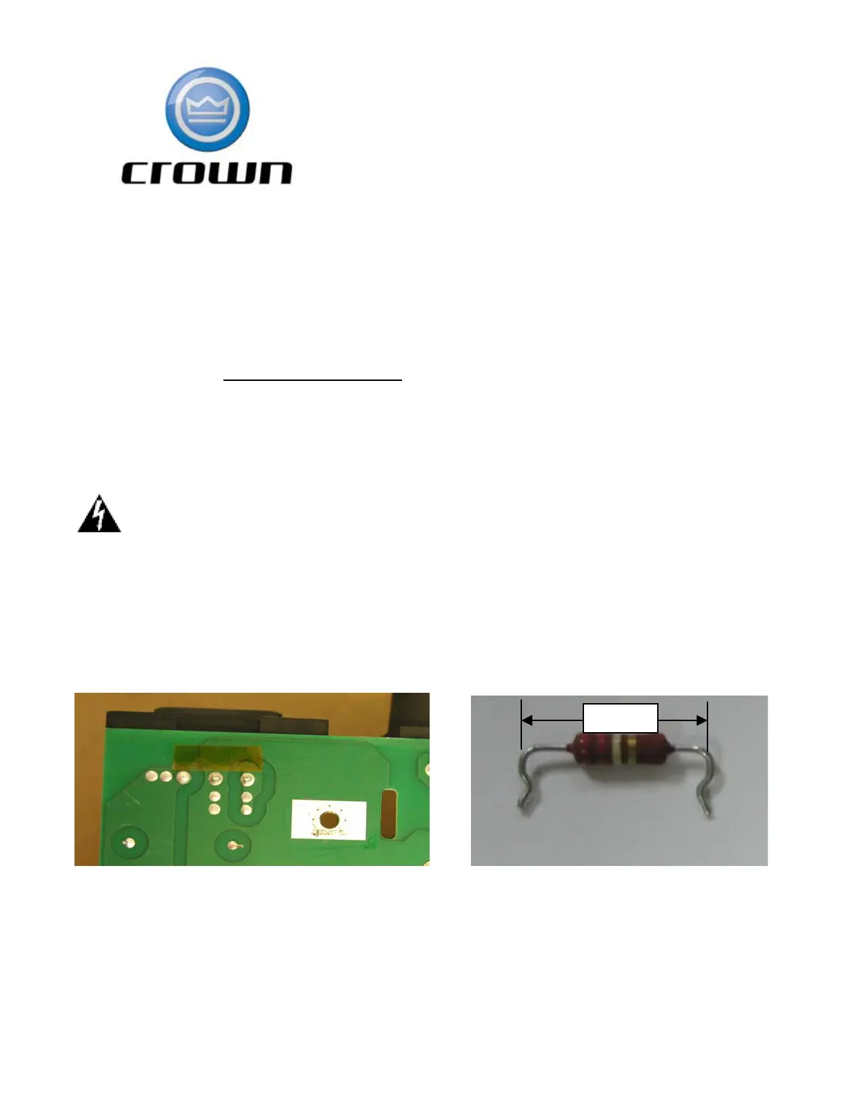
Step 2: Add a piece of Kapton tape (0.04mm thick x 7mm (W) x 20mm(L) minimum) over
ground trace to provide insulation between the resistor body and trace. Use, (CPN A10266-
2244); 220 KOhm, 2W, 5%, metal film type, resistor. See Figure 1 and 2 below.
Figure 1 Figure 2
15m
 Loading...