Installation
DS 400 Side 8 of 36
4 Installation
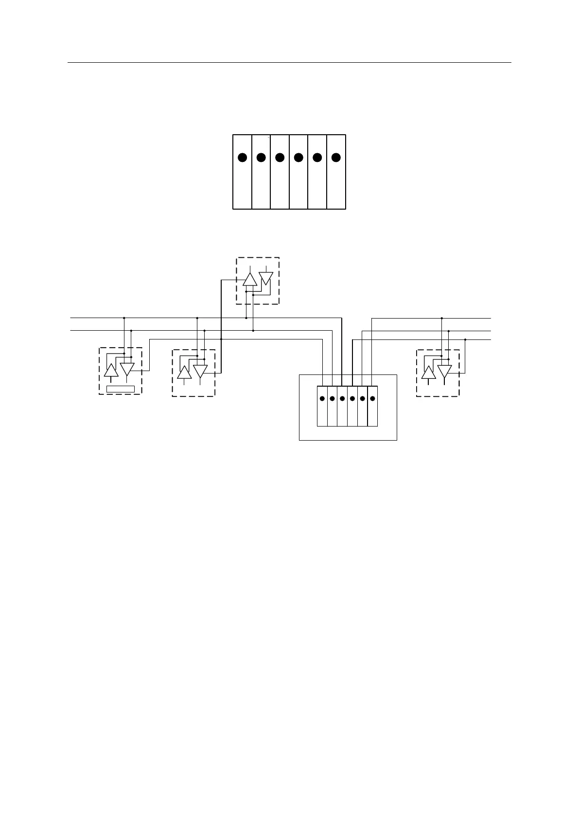
4.1 RS485 bus wiring (Modbus RTU) – Connection diagram connector „E“
1 2 3 4 5 6
Common
RS485 (B)
RS485 (A)
Common
RS485 (B)
RS485 (A)
Slave 1
Slave n
A
B
Common
T
T
R
R
Master
T
R
1 2 3 4 5 6
C
o
m
m
o
n
R
S
4
8
5
(B
)
R
S
4
8
5
(A
)
C
o
m
m
o
n
R
S
4
8
5
(B
)
R
S
4
8
5
(A
)
DS 400 Ethernet Board Stecker „E“
A
B
Common
Slave n
T
R
Bus cable:
Only cables according to the recommendations of EIA 485 standard should be used. A
maximum of 64 devices may be connected to one segment. The bus cable must be laid at
a distance of at least 20 cm from other cables. It should be laid in a separate, conductive,
and earthed cable trunking. It must be ensured that no potential differences occur between
the individual devices on the bus.
Cable specification:
Impedance: 135 -165 Ohm @ 3 to 20 Mhz
Cable capacity: < 30pF/m
Cable diameter: > 0.64 mm
Cross section: > 0.34 mm2, conforms to AWG 22
Loop resistance < 110 Ohm per km
Screening: Cu shielding braid or shielding braid and shielding foil