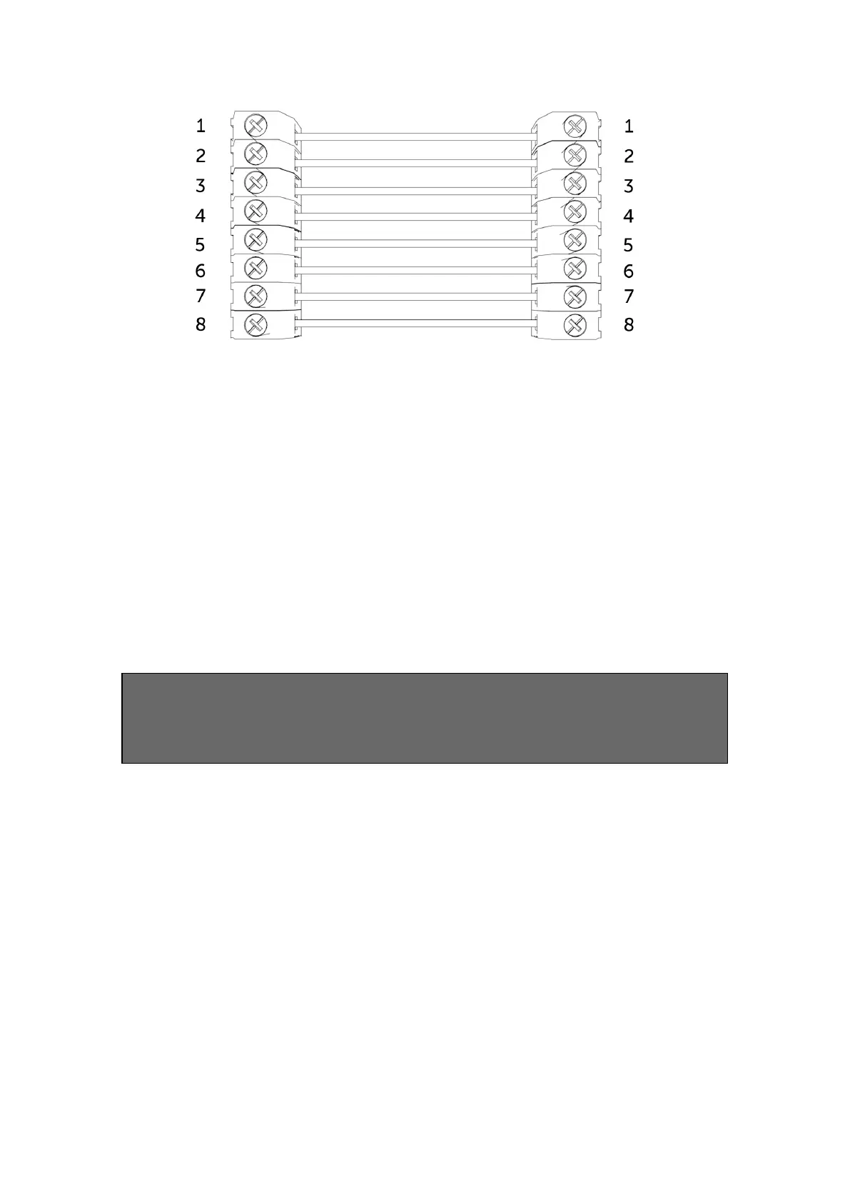
Figure 5 – Example of pin triggering wiring
CONFIGURING PIN INPUTS
To self-learn the current panel input status, press button C whilst in
quiescent/normal state for 5 seconds. LED 3 will flash red twice once completed.
To change the input from negative removed or applied to positive removed or
applied, change the pin bias via My Base under the Hardware menu button and use
the A+ terminal instead of RTN.
IF YOU CANNOT CHANGE THE PANEL’S POLARITY AND YOU DO NOT HAVE
ACCESS TO MY BASE OR THE WEBSITE, PLEASE SPEAK TO OUR TECHNICAL
SUPPORT TEAM.
DualCom Pro pin inputs 1, 2, 3, 5 – 8 generate SIA untyped alarms UA/UR8001 to
8012 on standard product configuration e.g.
[#123456|NUA8001|AChannel 1 Alarm]
[#123456|NUR8001|AChannel 1 Restore]
DualCom Pro pin 4 Open / Close inputs generate SIA alarm OP and CL OP/CL8004 on
standard product configuration e.g.
[#123456|NOP8004|ASystem Set]
[#123456|NCL8004|ASystem Unset]
CONFIGURING OUTPUTS
Both outputs can be configured as either Normally Open (NO) or Normally Closed
(NC), as required. Output 1 is defaulted to indicate a total path fail condition to the
 Loading...
