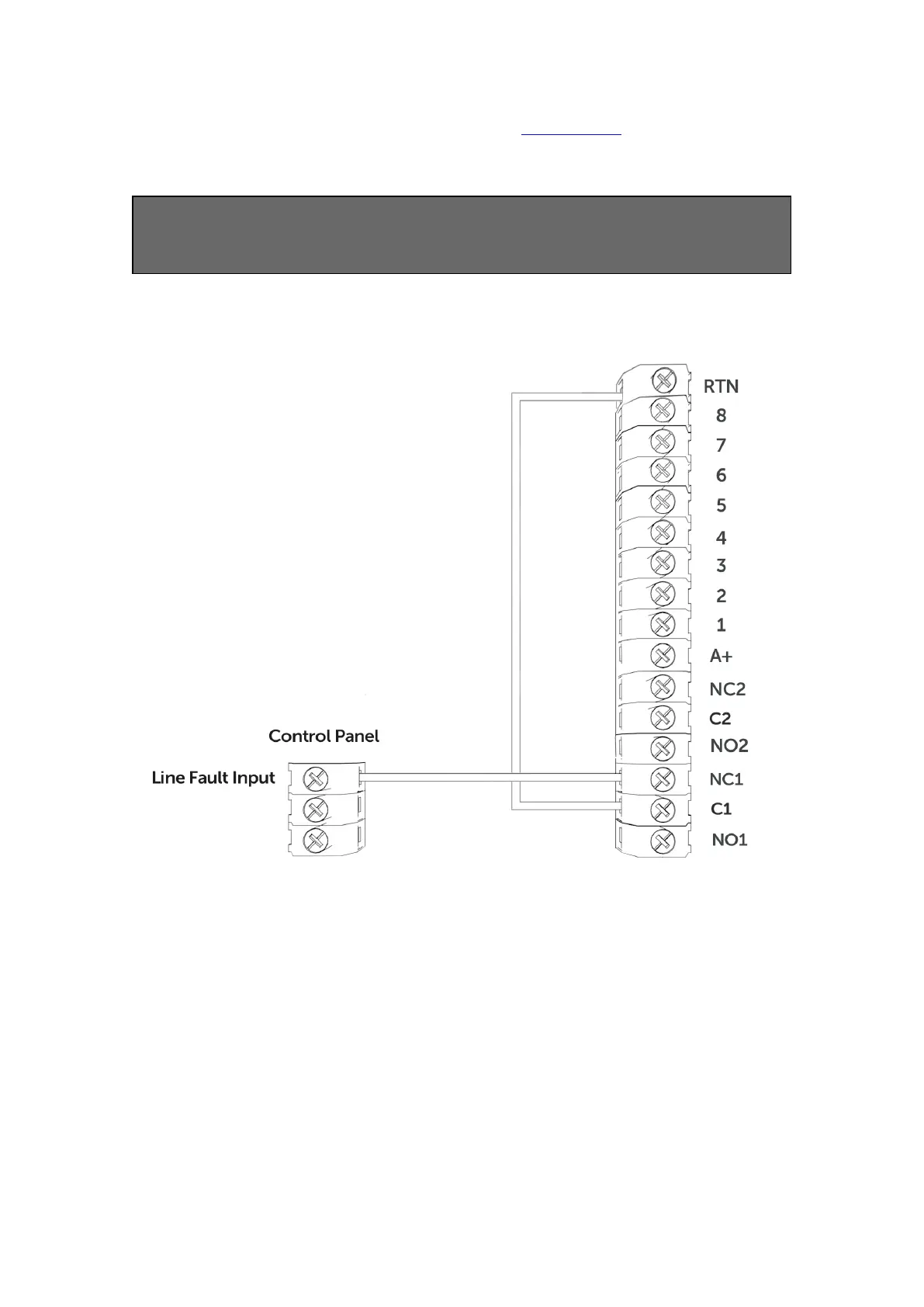
control panel. Output 1 can be reconfigured to indicate another path failure type,
Output 2 can be configured to indicate a path fail condition or be used as a manual
trigger. To make any amendments please use the My Base App.
IF THE DEVICE IS POWERED BY A 24V (FIRE PANEL) SUPPLY, THE A+
TERMINAL WILL STILL DELIVER 12V
Figure 6 - Example of Fault Output Wiring
PANEL CONNECTIONS
DIAL CAPTURE
DigiAir Pro 3 simulates and replaces the phone line connection to the control panel’s
Digi-Modem. The control panel’s Digi-Modem must use one of the following alarm
formats: Fast Format*, Contact ID or SIA. In the event the control panel needs to
send a signal to the ARC, DigiAir Pro 3 will capture the message and forward it, via
Gemini, to the ARC. The Digi-Modem must have an ARC telephone number (ie 01)
 Loading...
