8
5(10)
161 145 07 02-01
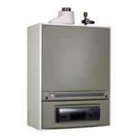
02. INSTALLATION
1. Flue outlet diam 82 mm internal
with high temp sealing diam 80 mm
2. Air inlet hose diam 80 mm internal
3. Flow G 1 ½” (nut), alt G 1” internal
4. Return G 1 ½” (nut), alt G 1” internal
5. Flow to hot water tank G 3/4” internal
6. Return from hot water tank G 3/4” external
7. Mixing valve
2.2 CTC 950 with hot water tank and one heating circuit
• Pipe kit (P/N 579990301) 1-circuit, assembly instr. see chapter 06.
• Mixing valve (P/N 912912401)
• Electrical diagram D-580097.
Dimensions