16
03 ELECTRICAL INSTALLATION
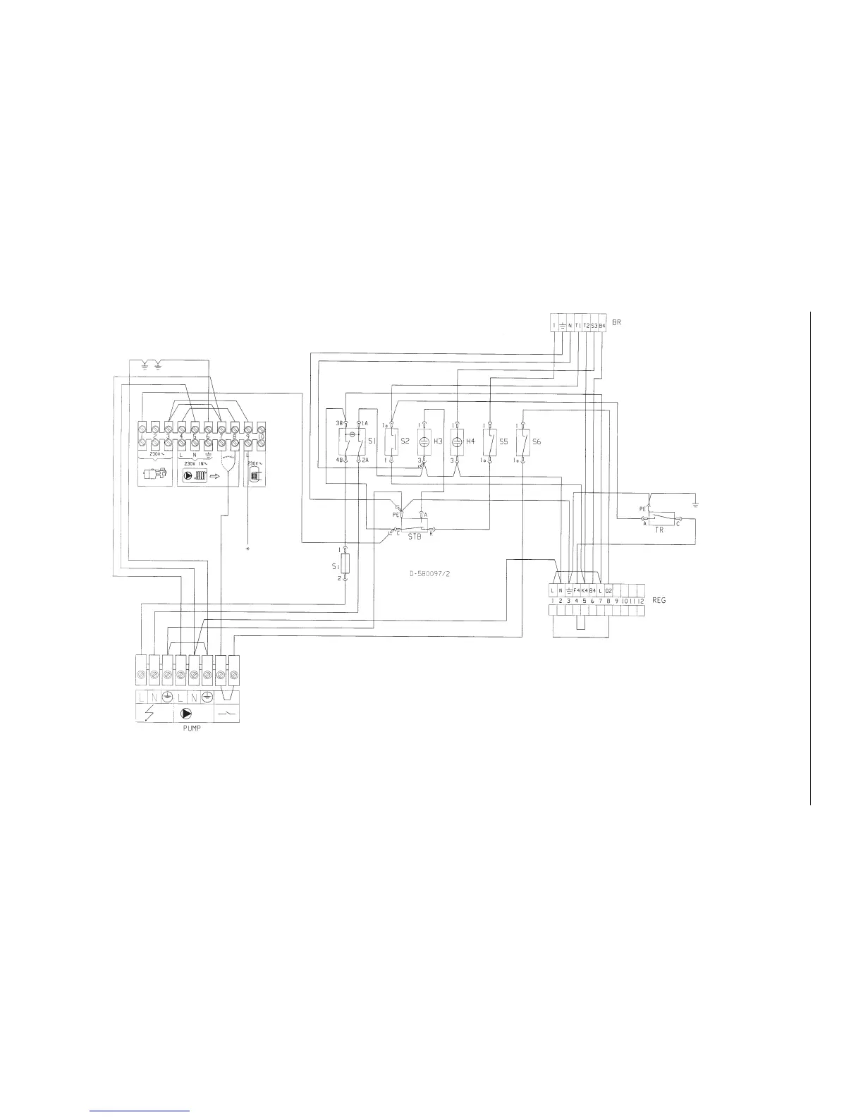
3.3 Electrical diagram D-580097: CTC 950 with hot water tank and mixing valve
S1 Main switch for boiler
S2 TÜV switch
H3 Lamp safety thermostat
H4 Lamp burner fault
S5 Switch for burner
S6 Switch for circulation pump
STB Safety thermostat
TR Control thermostat
S1 Fuse8
BR Eurostecker for burner
REG Terminal block (regulation)
VVX Micro switch heat exchangr (option)
PUMP Pump forhot water tank
Signal on terminal No 9 will start the pump for hot water tank
3(4)
161 215 06 02-02