10 Section 3— ASSembly & Set-Up
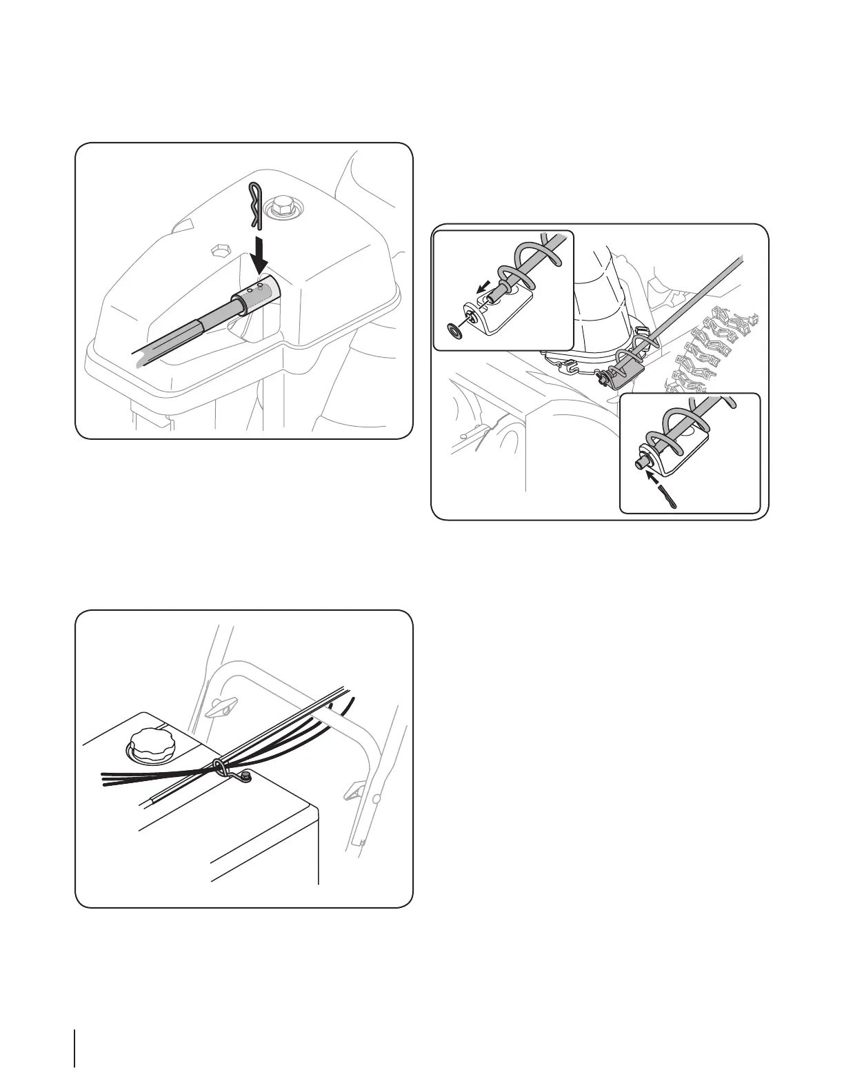
NOTE: For smoothest operation, the cables should all be to
the left of the chute directional control rod.
NOTE: Models with 2-Way Chute Control have only one
cable to route through the cable guide.
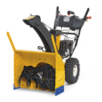
Chute Directional Control (Side Crank) (If Equipped)
1. Remove the plastic cap (if present), flat washer and hairpin
clip from the end of the chute directional control. See
Figure 3-11.
Figure 3-11
2. Insert the end of the chute directional control into the
lower bracket and secure with the flat washer and hairpin
clip just removed. If necessary, the lower bracket can be
adjusted. Refer to Chute Bracket Adjustment in the Service
section.
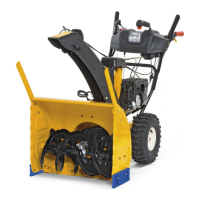
7. Push the chute control rod toward the control panel until
the hole in the rod lines up with the hole in the chute
control input closest to the chute control head and insert
the hairpin clip removed earlier. See Figure 3-9.
Figure 3-9
NOTE: The second hole is used to achieve further
engagement of the chute control rod into the pinion gear if
required. Refer to page 22 for Chute Control Rod adjustments.
8. Finish securing chute control head to chute support
bracket with wing nut, clevis pin, and bow-tie cotter pin
removed in step 1. See Figure 3-3.
9. Check that all cables are properly routed through the cable
guide on top of the engine. See Figure 3-10.
Figure 3-10

 Loading...