N
OTE: The blade retainer under the cutting
a
ttachment will be used when installing the
c
utting blade.
I
nstall the Cutting Blade
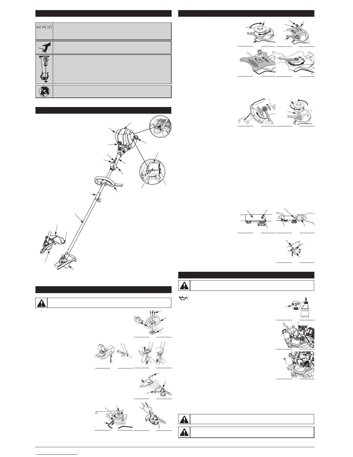
4
. Place the cutting blade on the output shaft
b
ushing (Fig. 8).
5
. Make sure that the cutting blade is centered on
the pilot step and sitting flat against the output
shaft bushing (Fig. 9).
6. Align the shaft bushing hole with the locking rod
slot and insert the locking rod into the bushing
hole (Fig. 5).
7. Put the blade retainer and nut on the output shaft.
Make sure that the blade is installed correctly.
8. Tighten nut counterclockwise against the blade
w
hile holding the locking rod:
•
If using a torque wrench and a 13 mm socket
t
ighten to: 325 - 335 in•lb, 27 - 28 ft.•lb, 37 - 38
N•m.
• Without a torque wrench, use a 13 mm closed-
end or socket wrench, turning the nut until the blade retainer is snug against the shaft bushing. Make sure that the
b
lade is installed correctly, then rotate the nut an additional 1/4 to 1/2 turn counterclockwise (Fig. 10).
9. Remove the locking rod from the locking rod slot.
REMOVE THE CUTTING BLADE AND INSTALL THE CUTTING ATTACHMENT
Remove the Cutting Blade
1
. Align the shaft bushing hole with the locking rod
slot and insert the locking rod into the bushing
hole (Fig. 5).
2. Hold the locking rod in place by grasping it next
to the boom of the unit (Fig. 11).
3. While holding the locking rod, loosen the nut on
the blade by turning it clockwise with a 13 mm
c
losed-end or socket wrench (Fig. 11).
4
. Remove the nut, blade retainer and blade. Store
the nut and blade together for future use in a
s
ecure place. Store out of children’s reach.
Install the Cutting Attachment
5
. Align the shaft bushing hole with the locking rod slot and insert the locking rod into the shaft bushing hole (Fig. 5).
P
lace the blade retainer on the output shaft with the flat surface against the output shaft bushing (Fig. 12). Screw
the cutting attachment counterclockwise onto the output shaft. Tighten securely.
N
OTE: The blade retainer must be installed on the output shaft in the position shown for the cutting attachment to
w
ork correctly.
6. Remove the locking rod.
7. Install the cutting attachment shield. Refer to Remove and Install the Cutting Attachment Shield.
O
PERATING THE RAPID LINK™ SYSTEM
T
he Rapid Link™ system enables the use of these optional Add-Ons.
T
rimmer. . . . . . . . . . . . . . . . . . . . . . . . . . . . . . . . . . . . . . . . . . . . . . . . . . . . . . . . . . . . . . . . . . . . . . . . . . . . . . . . . . . AF720
H
edge Trimmer . . . . . . . . . . . . . . . . . . . . . . . . . . . . . . . . . . . . . . . . . . . . . . . . . . . . . . . . . . . . . . . . . . . . . . . . . . . AH720*
B
rushcutter. . . . . . . . . . . . . . . . . . . . . . . . . . . . . . . . . . . . . . . . . . . . . . . . . . . . . . . . . . . . . . . . . . . . . . . . . . . . . . . BC720*
C
ultivator . . . . . . . . . . . . . . . . . . . . . . . . . . . . . . . . . . . . . . . . . . . . . . . . . . . . . . . . . . . . . . . . . . . . . . . . . . . . . . . . GC720
E
dger . . . . . . . . . . . . . . . . . . . . . . . . . . . . . . . . . . . . . . . . . . . . . . . . . . . . . . . . . . . . . . . . . . . . . . . . . . . . . . . . . . . LE720*
P
ole Saw . . . . . . . . . . . . . . . . . . . . . . . . . . . . . . . . . . . . . . . . . . . . . . . . . . . . . . . . . . . . . . . . . . . . . . . . . . . . . . . . . PS720
S
traight Shaft Trimmer . . . . . . . . . . . . . . . . . . . . . . . . . . . . . . . . . . . . . . . . . . . . . . . . . . . . . . . . . . . . . . . . . . . . . . SS725
Turbo Blower . . . . . . . . . . . . . . . . . . . . . . . . . . . . . . . . . . . . . . . . . . . . . . . . . . . . . . . . . . . . . . . . . . . . . . . . . . . . . . TB720
* Do NOT use this Add-On with an electric powered unit.
REMOVING THE ADD-ON
1. Turn the knob counterclockwise to loosen (Fig. 15).
2. Press and hold the release button (Fig. 13).
3
. While firmly holding the upper shaft housing,
pull the lower shaft housing straight out of the
R
apid Link™ coupler (Fig. 14).
I
nstalling the Add-On
NOTE: To make installing or removing the add-on
e
asier, place the unit on the ground or on a
w
ork bench.
1
. Turn knob counterclockwise to loosen (Fig. 15).
2.
While firmly holding the add-on, push it straight
into the Rapid Link™ coupler (Fig. 14).
NOTE: Aligning the release button with the guide recess will help installation (Fig. 13).
3. Turn the knob clockwise to tighten (Fig. 15).
F
or decorative trimming/edging with the line cutting head, lock the release button
into the 90° hole (Fig. 15).
3
KNOW YOUR UNIT
APPLICATIONS
As a trimmer:
•
Cutting grass and light weeds.
•
Edging
•
Decorative trimming around trees,
fences, etc.
A
s a brushcutter:
•
Cut heavy grass and weeds up to 1/2”
(1.3 cm) diameter.
Throttle Control
D-Handle
S
haft Grip
Air Filter/Muffler
C
over
Spark Plug
Shaft Housing
Starter Rope Grip
Line Cutting
Blade
Muffler
On/Off Control
Cutting Head
Cutting Head Shield
Fuel Cap
Rapid Link™
OIL AND FUEL INFORMATION
INSTALL AND ADJUST THE D-HANDLE
1. Remove the screws and bottom clamp piece that were installed on the D-handle
for shipping.
2. Place D-handle over the shaft housing and onto the bottom clamp (Fig. 1). Place it
a minimum of 6 inches (15.24 cm) from the end of the shaft grip.
3. Start screws with a large Flat-head or T-25 Torx screwdriver. Do not tighten until
making the handle adjustment.
4. If it was pre-installed, loosen the screws on the D-handle just enough to move the
D-handle.
5. While holding the unit in the operating position (Fig. 23), move the D-handle to the
location that provides you the best grip.
6.
Tighten the clamp screws evenly, until the D-handle
is secure.
INSTALL THE HARNESS
1. Push the strap through the center of the buckle.
2. Pull the strap over the cross bar and down
through the slot in the buckle (Fig. 2).
3. Put the harness on over head and onto shoulder.
Snap it on to the support fitting (Fig. 2).
4. Adjust length to fit the operator’s size. Pull tab
to lengthen, pull strap to shorten (Fig. 3).
REMOVE AND INSTALL THE CUTTING ATTACHMENT SHIELD
Remove the cutting attachment shield when using the unit as a brushcutter
Remove the cutting attachment shield from the shield mount by removing the three
(3) screws with a flat blade screwdriver (Fig. 4). Store parts for future use.
Install the cutting attachment shield when using the unit as a grass trimmer
Install the cutting attachment shield on the shield mount by inserting the three (3)
screws into the shield mount. Tighten securely with a flat blade screwdriver (Fig. 4).
REMOVE THE CUTTING ATTACHMENT AND INSTALL THE CUTTING BLADE
NOTE: To make cutting blade removal and
installation easier, place the unit on the ground
or on a work bench.
Remove the Cutting Attachment Shield
See Remove and Install the Cutting Attachment
Shield.
Remove the Cutting Attachment
1. Align the shaft bushing hole with the locking rod
slot and insert the locking rod into the shaft
bushing hole (Fig. 5).
2. Hold the locking rod in place by grasping it next to the boom of the unit (Fig. 6).
3. While holding the locking rod, remove the cutting attachment by turning it clockwise off of the output shaft (Fig. 7).
Store the cutting attachment for future use.
ASSEMBLY INSTRUCTIONS
Guide Recess
Fig. 13
R
elease Button
Rapid Link™
Coupler
Upper Shaft
H
ousing
Fig. 14
Lower Shaft
H
ousing
P
rimary Hole
K
nob
Fig. 15
9
0˚ Edging Hole
(
Trimmer Only)
• CHOKE CONTROL
1. • FULL choke position
2. • PARTIAL choke position
3. • RUN choke position
• SHARP BLADE
WARNING: Sharp blade on cutting attachment shield. To prevent serious injury, do
not touch the line cutting blade.
WARNING:
To prevent serious personal injury, never operate the trimmer without the cutting
attachment shield in place.
Min 6 in.
(15.32 mm)
Screw (4)
D-Handle
Fig. 1
Fig. 2
O
il Fill Plug
B
lue Choke Lever
Primer
Bulb
WARNING:
Overfilling oil crankcase may cause serious personal injury. Check and maintain the
p
roper oil level in the crank case; it is important and cannot be overemphasized. Check the oil before
each use and change it as needed. See Changing the Oil.
RECOMMENDED OIL TYPE
Using the proper type and weight of oil in the crankcase is extremely
important. Check the oil before each use and change the oil regularly. Failure
to use the correct oil, or using dirty oil, can cause premature engine wear and failure.
Use a high-quality SAE 30 weight oil of API (American Petroleum Institute) service
class SF, SG, SH.
ADDING OIL TO CRANKCASE: INITIAL USE
NOTE: This unit is shipped without oil. In order to avoid damage to the unit, put oil in
the crankcase before you attempt to start the unit.
Your unit is supplied with one 3.04 fluid oz. (90 ml) bottle of SAE 30 SF, SG, SH oil
(Fig. 16).
NOTE: Save the bottle of oil. It can be used to measure the correct amount during
future oil changes. See Changing the Oil.
1. Unscrew the top of the bottle of oil and remove the paper seal covering the
opening. Replace the top. Next, cut the tip off the funnel spout (Fig. 16).
2. Tip unit so that the back of the engine is facing up in a vertical position.
3. Remove the oil fill plug from the crankcase (Fig. 18).
4. Pour the entire bottle of oil into the oil fill hole (Fig. 17).
NOTE: Never add oil to the fuel or fuel tank.
5. Wipe up any oil that may have spilled and reinstall the oil fill plug.
Check oil before each use and change as needed. Refer to Checking the Oil Level.
RECOMMENDED FUEL TYPE
Old fuel is the primary reason for improper unit performance. Be sure to use fresh,
clean, unleaded gasoline.
NOTE: This is a four cycle engine. In order to avoid damage to the unit, do not mix
oil with gasoline.
Definition of Blended Fuels
Today's fuels are often a blend of gasoline and oxygenates such as ethanol, methanol or MTBE (ether). Alcohol-
blended fuel absorbs water. As little as 1% water in the fuel can make fuel and oil separate or form acids when stored.
Use fresh fuel (less than 30 days old), when using alcohol-blended fuel.
Using Blended Fuels
If you choose to use a blended fuel, or its use is unavoidable, follow recommended precautions:
• Always use fresh unleaded gasoline
• Use the fuel additive STA-BIL® or an equivalent
• Drain tank and run the engine dry before storing unit
USING FUEL ADDITIVES
Funnel
Spout
Fig. 16
SYMBOL MEANING
RULES FOR SAFE OPERATION
• TRIMMER/ BRUSHCUTTER SAFETY
W
ARNING:
Thrown objects and rotating cutter can cause severe injury. Keep
bystanders, especially children and pets, at least 50 feet (15 m) away from the cutting area.
The cutting attachment shield must be used when using the trimmer cutting attachment.
• BRUSHCUTTERS • REPLACE DULL BLADE
Do not sharpen the cutting blade. Sharpening the blade can cause the blade tip to
break off while in use. This can result in severe personal injury.
Fig. 3
Screws (3)
Cutting
Attachment
Shield
Fig. 4
Gearbox
Shield
Mount
Shaft
Bushing Hole
Output Shaft
Output
Shaft
Bushing
Fig. 5
Fig. 6
Cutting Attachment
Locking Rod
Fig. 7
N
ut
C
utting Blade
Fig. 8
Blade
Retainer
S
hield
Mount
Pilot
H
ole
P
ilot
Step
Fig. 9
Fig. 10
Clockwise
F
ig. 11
Cutting
Attachment
Fig. 12
B
lade
Retainer
ASSEMBLY INSTRUCTIONS
B
rushcutter Blade
Throttle Lockout
Bottom
Clamp
Locking
Rod Slot
Locking
Rod
Fig. 18
Oil Fill
Plug
O-Ring
Fig. 17
Oil Fill
Hole
WARNING:
Add fuel in a clean, well ventilated outdoor area. Wipe up any spilled fuel immediately.
Avoid creating a source of ignition for spilt fuel. Do not start the engine until fuel vapors dissipate.
T
ools Required:
•
Flat blade screwdriver
•
T-25 Torx screwdriver
•
Locking Rod
•
13 mm closed-end or socket wrench
WARNING:
Gasoline is extremely flammable. Ignited vapors may explode. Always stop the engine
and allow it to cool before filling the fuel tank. Do not smoke while filling the tank. Keep sparks and open
flames at a distance from the area.
 Loading...