ELECTRIC STARTER AND POWER START BIT™ FEATURES
This unit is designed to be started with an optional
electric starter or Power Start Bit™, which are sold
separately. If choosing to start the unit using one of
these features or have questions, please contact
your local retailer or call 1-800-282-8684 in the U.S.
(1-800-668-1238 in Canada) for more information
and purchasing. You may also go to
www.cubcadet.com or www.cubcadet.ca.
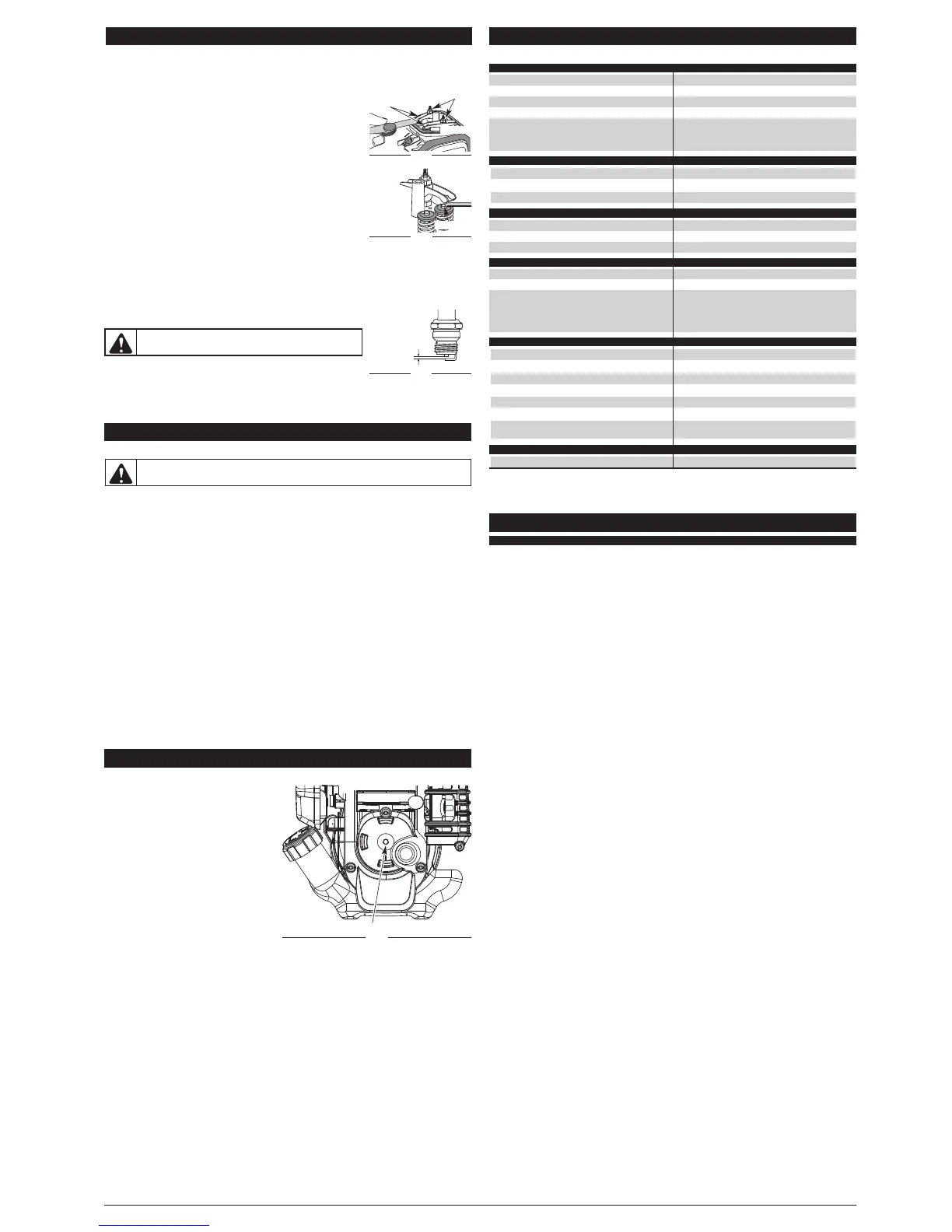
ROCKER ARM CLEARANCE
7. Slide the feeler gauge between the rocker arm and the valve return spring. Measure the clearance
between the valve stem and rocker arm (Fig. 46). Measure both the intake and exhaust valves.
The recommended clearance for both intake and exhaust is .003 – .006 in.
(.076 – 0.152 mm). Use a standard automotive .005 in. (0.127 mm) feeler
gauge. The feeler gauge should slide between the rocker arm and valve
stem with a slight amount of resistance, without binding. See Figures 46
and 47.
8. If the clearance is not within specification:
a. Turn the adjusting nut using a 5/16 inch (8 mm) wrench or nut driver
(Fig. 46).
• To increase clearance, turn the adjusting nut counterclockwise.
• To decrease clearance, turn the adjusting nut clockwise.
b. Recheck both clearances and adjust as necessary.
9. Reinstall the rocker arm cover using a new gasket. Torque the screw to
20–30 in•lb (2.2–3.4 N•m).
10. Check the spark plug and reinstall. See Replacing the Spark Plug.
11. Replace the spark plug wire.
12. Reinstall the engine cover. Check alignment of the cover before
tightening the screws. Tighten screws.
C
AUSE
A
CTION
66
O
ld fuel (over 30 days)
D
rain fuel tank and add fresh fuel
F
ouled spark plug
R
eplace or clean the spark plug
The outside temperature is above 90˚ F
M
ove the choke lever to Position 2, press the primer
bulb 10 times, squeeze the throttle control and pull the
starter rope until the unit starts. Run the unit for 2-5
minutes. The unit may be used during this time. Then
move the choke lever to Position 3.
Old fuel (over 30 days) Drain gas tank and add fresh fuel
C
utting attachment bound with grass
S
top the engine and clean the cutting attachment
Dirty air filter Clean or replace the air filter
C
utting attachment bound with grass
S
top the engine and clean cutting attachment
C
utting attachment out of line
R
efill with new line
Inner reel bound up Replace the inner reel
C
utting head dirty
C
lean inner reel and outer spool
L
ine welded
D
isassemble, remove the welded section and rewind
L
ine twisted when refilled
D
isassemble and rewind the line
Not enough line is exposed
Push the bump head and pull out line until 4 inches
(
102 mm) of line is outside of the cutting attachment
Oil, cleaner or lubricant in cutting head Clean and thoroughly dry the cutting head
TROUBLESHOOTING
E
mpty fuel tank
F
ill fuel tank with fuel
P
rimer bulb wasn't pressed enough
P
ress primer bulb fully and slowly 10 times
O
ld fuel (over 30 days)
D
rain fuel tank and add fresh fuel
F
ouled spark plug
R
eplace or clean the spark plug
Engine is over heated
Move the choke lever to Position 2, squeeze the throttle
control and pull the starter rope until the unit starts. Run
t
he unit for 2-5 minutes. Then move the choke lever to
P
osition 3.
Air filter is plugged Replace or clean the air filter
O
ld fuel (over 30 days) Drain fuel tank and add fresh fuel
Improper idle speed Adjust according to the Idle Speed Adjustment section
E
NGINE WILL NOT START
ENGINE WILL NOT ACCELERATE
ENGINE WILL NOT IDLE
IF FURTHER ASSISTANCE IS REQUIRED, CONTACT YOUR AUTHORIZED SERVICE DEALER.
ENGINE LACKS POWER OR STALLS WHEN CUTTING
CUTTING ATTACHMENT WILL NOT ADVANCE LINE
CUTTING LINE ADVANCES UNCONTROLLABLY
U
NIT*
Engine Type. . . . . . . . . . . . . . . . . . . . . . . . . . . . . . . . . . . . . . . . . . . . . . . . . . . . . . . . . . . . . . . . . . . . Air-Cooled, 4-Cycle
Displacement . . . . . . . . . . . . . . . . . . . . . . . . . . . . . . . . . . . . . . . . . . . . . . . . . . . . . . . . . . . . . . . . . . . . 1.8 cu. in. (29 cc)
Operating RPM . . . . . . . . . . . . . . . . . . . . . . . . . . . . . . . . . . . . . . . . . . . . . . . . . . . . . . . . . . . . . . . . . . . . . . . . 6,800+ rpm
Idle Speed RPM. . . . . . . . . . . . . . . . . . . . . . . . . . . . . . . . . . . . . . . . . . . . . . . . . . . . . . . . . . . . . . . . . . 2,800 - 3,600 rpm
V
alve clearance . . . . . . . . . . . . . . . . . . . . . . . . . . . . . . . . . . . . . . . . . . . . . . . . . . . . . 0.003–0.006 in. (0.076–0.152 mm)
S
park Plug Gap. . . . . . . . . . . . . . . . . . . . . . . . . . . . . . . . . . . . . . . . . . . . . . . . . . . . . . . . . . . . . . . 0.025 inch (0.655 mm)
L
ubrication . . . . . . . . . . . . . . . . . . . . . . . . . . . . . . . . . . . . . . . . . . . . . . . . . . . . . . . . . . . . . . . . . . . . . . . . . . . . SAE 30 Oil
C
rankcase Oil Capacity . . . . . . . . . . . . . . . . . . . . . . . . . . . . . . . . . . . . . . . . . . . . . . . . . . . . . . . . . . . . . . 3.04 oz (90 ml)
F
uel . . . . . . . . . . . . . . . . . . . . . . . . . . . . . . . . . . . . . . . . . . . . . . . . . . . . . . . . . . . . . . . . . . . . . . . . . . . . . . . . . . Unleaded
F
uel Tank Capacity . . . . . . . . . . . . . . . . . . . . . . . . . . . . . . . . . . . . . . . . . . . . . . . . . . . . . . . . . . . . . . . . . . . 14 oz (414 ml)
A
pproximate Unit Weight (No fuel, with handle, cutting attachment and shield). . . . . . . . . . . . . . 12-13.5 lbs (5.4-6 kg)
Trimming Line Diameter . . . . . . . . . . . . . . . . . . . . . . . . . . . . . . . . . . . . . . . . . . . . . . . . . . . . . . . 0.105 inches (2.67 mm)
Cutting Path Diameter, Trimmer Head . . . . . . . . . . . . . . . . . . . . . . . . . . . . . . . . . . . . . . . . . . . . . . . 18 inches (45.7 cm)
Cutting Path Diameter, Blade Head . . . . . . . . . . . . . . . . . . . . . . . . . . . . . . . . . . . . . . . . . . . . . . . . . . 8 inches (204 mm)
Shoulder Harness . . . . . . . . . . . . . . . . . . . . . . . . . . . . . . . . . . . . . . . . . . . . . . . . . . . . . . . . . . . . . . . . Single Quick-Snap
SPECIFICATIONS
*
All specifications are based on the latest product information available at the time of printing. We reserve the right to
make changes at any time without notice.
CLEANING
Use a small brush to clean off the outside of the unit. Do not use strong detergents. Household cleaners
that contain aromatic oils such as pine and lemon, and solvents such as kerosene, can damage plastic
housing or handle. Wipe off any moisture with a soft cloth.
STORAGE
• Never store the unit with fuel in the tank where fumes may reach an open flame or spark.
• Allow the engine to cool before storing.
• Lock up the unit to prevent unauthorized use or damage.
• Store the unit in a dry, well-ventilated area.
• Store the unit out of the reach of children.
Short Term Storage (1-2 weeks)
1. Store the unit in a horizontal position. If this is not possible, store the unit vertically with the engine at
the top.
Long Term Storage
1. Drain all gasoline from the gas tank into a container. Do not use gas that has been stored for more
than 30 days. Dispose of the old gasoline in accordance with federal, state and local regulations.
2. Start the engine and allow it to run until it stalls. This ensures that all gasoline has been drained from
the carburetor.
3. Allow the engine to cool. Remove the spark plug and put 5 drops of high quality motor oil into the
cylinder. Pull the starter rope slowly to distribute the oil. Reinstall the spark plug.
NOTE: Remove the spark plug and drain all of the oil from the cylinder before attempting to start the
trimmer after storage.
4. Change the oil, referring to Changing the Oil. Dispose of the old oil in accordance with federal, state
and local regulations.
5. Thoroughly clean the unit and inspect for any loose or damaged parts. Repair or replace damaged
parts and
tighten loose screws, nuts or bolts. The unit is ready for storage.
REPLACING THE SPARK PLUG
Use a replacement part number 753-05784 or Champion
®
#RDZ4H spark plug. The correct air gap is 0.025 in. (0.635
m
m).
1
. Stop the engine and allow it to cool. Remove the six (6) screws on the back of the engine cover with a Flat-head or
T
-25 Torx screwdriver (Fig. 44).
2
. Grasp the plug wire firmly and pull the cap from the spark plug.
3
. Clean dirt from around the spark plug. Remove the spark plug from the cylinder
h
ead by turning a 5/8 in. socket counterclockwise.
4
. Replace cracked, fouled or dirty spark plug. Set the air gap at 0.025 in. (0.635 mm.)
u
sing a feeler gauge (Fig. 48).
5
. Install a correctly-gapped spark plug in the cylinder head. Turn the 5/8 in. socket
c
lockwise until snug.
I
f using a torque wrench torque to: 110-120 in.•lb. (12.3-13.5 N•m)
D
o not over tighten.
t
ighten loose screws, nuts or bolts. The unit is ready for storage.
MAINTENANCE AND REPAIR INSTRUCTIONS
WARNING:
To avoid serious personal injury, always turn the unit off and allow it to cool
before cleaning or servicing it.
WARNING:
Do not sand blast, scrape or clean electrodes.
Grit in the engine could damage the cylinder.
Fig. 48
0.025 in.
(0.635 mm.)
CLEANING AND STORAGE
Fig. 46
Adjustment
Nuts
I
ntake
Exhaust
Rocker
Arms
Valve Stem
Fig. 47
OPTIONAL ACCESSORY
Fig. 49
Electric Start Feature
 Loading...