351804-1 Rev. 100
COM5000-8 TECHNICAL MANUAL
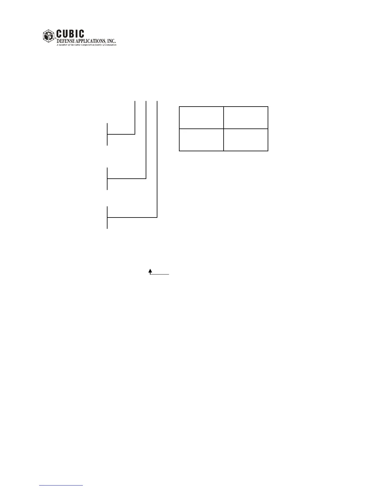
Fault definition:
P X A
0 0 0
Bit 0 350W AMP 1A
Bit 1 350W AMP 1B
Bit 2 350W AMP 2A
Bit 3 350W AMP 2B
1.25 kW PA module front view.
Bit 0 Critical
Bit 1 Supply
Bit 2 Temperature
Bit 3 Filter
Bit 0 NA
Bit 1 FAN
Bit 2 Driver
Bit 3 VSWR
Example: Supply Fault = 0 2 0
Temperature fault in 350W AMP 1A = 1 4 0
Filter Fault = 0 9 0
Critical (Bit 0) + Filter (Bit 3)
See tables on next page for detailed decoding of faults.
The two Status screens may be used with the LED indicators on the PA module and the System Controller
module to locate a fault.
Note: The FWD and REV power readings on T-4180 Status screen #1 indicate the power measured
at the output connector of the Combiner. The power reading is for reference only and may
not match the reading of an external wattmeter - especially when operating into high VSWR
conditions.
The VSWR indicates the VSWR measured at the output connector of the Combiner. The
VSWR reading is for reference only and may not match the reading of an external wattmeter.