66 Culligan® CSM Series Softeners
66 Cat. No. 01016370
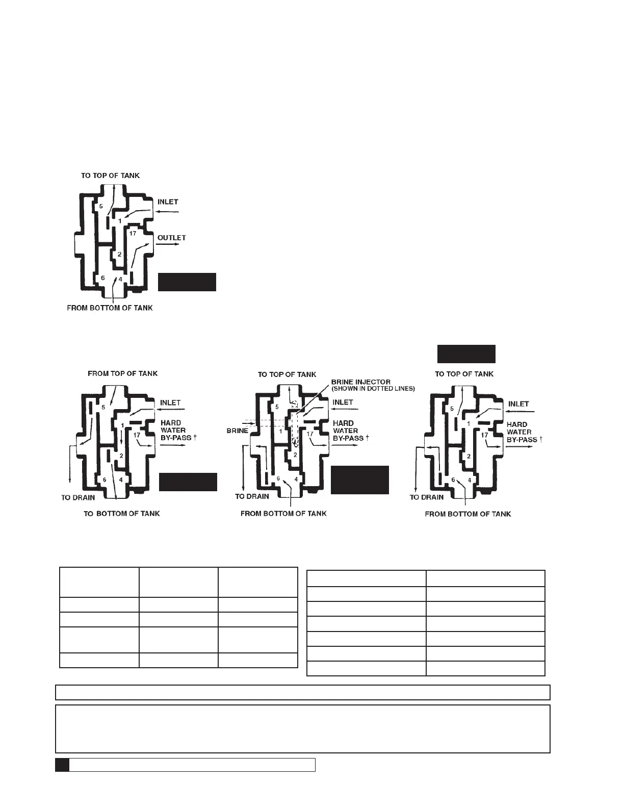
Brunermatic Valve Flow Diagrams & Flow Control Assembly Service
Flow patterns for the regeneration and service cycles are governed by the individual diaphragm valves. These valves
close when under pressure and open when pressure is vented. Each is identified by a number cast on the front of the
main valve body.
Control tubing connects each numbered valve with the MVP Controller.
SERVICE
BACKWASH
FLUSH
BRINE DRAW
SLOW RINSE
Figure 105.
Hard water by-pass valve normally used only on single unit.
Table 11.
Position Valves
(Vented)
Valves (Pres-
surized)
Service 1, 4 2, 5, 6, 17
Backwash 2, 5, 17 1, 4, 6
Brine Draw/ Slow
Rinse
6, 17 1, 2, 5, 4
Flush 1, 6, 17 2, 5, 4
Table 12. Port Conversion Chart
Old (Bruner) New (Culligan)
1 1
2 3
4 2
5 4
6 5
17 6
NOTE #17 is always closed on multiple tank systems. * See note below about port conversion.
NOTE * The system provided may utilize an older version of pilot valve and/or Brunermatic Valve port num-
bering. Evidence of the old numbering scheme is noted by the use of port number 17 on the pilot valve
and/or Brunermatic valve. If the numbering scheme of the pilot valve does not completely match the
Brunermatic valve, the following chart should be referred to for conversion purposes.

 Loading...


