Troubleshooting 57
Cat. No. 01023552
Flow Diagrams
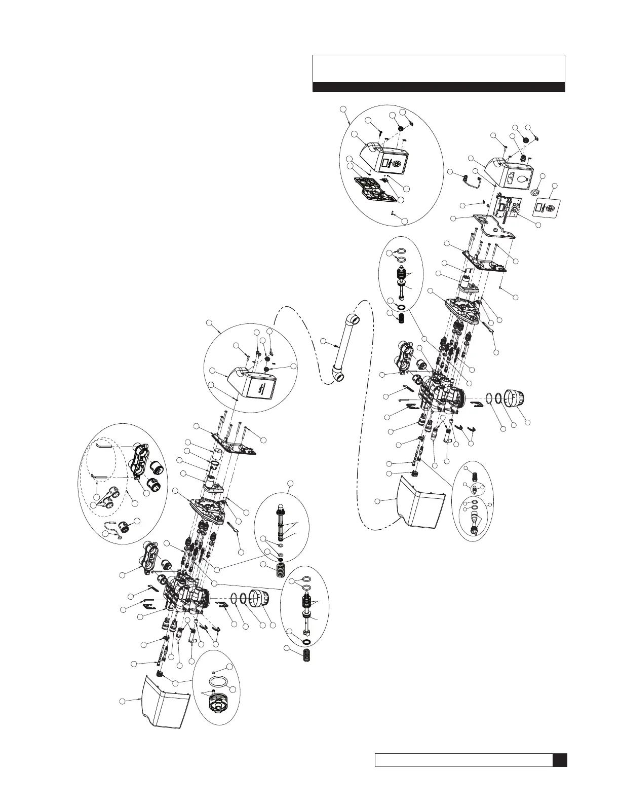
HE 1.5 Flow Valve Piston Locations
The flow valve controls the movement of untreated and treated product during downflow and upflow regeneration cycles.
Figure 65 identifies each piston as installed. For example, in this cycle (downflow service), the P1 and P2/P3 valves are
open; the P4, P5, P6, and PR valves and the Brine Piston are closed.
BRINE PISTON
P6
P1
P4
PR
P5
P2/P3
PISTONS
P1–Inlet Piston
P2/P3–Outlet Piston
P4–Backwash Piston
P5–Rinse Piston
P6–Bypass Piston
Brine–Brine Piston
PR–Refill Piston
Figure 65. HE 1.5 valve piston locations.
The cycle sequence is different for downflow regeneration than for upflow regeneration. Note the regeneration cycle se-
quence for downflow and upflow regeneration.
Downflow Regeneration Cycle Sequence
1. Service
2. Backwash
3. Brine Draw/Slow Rinse
4. Fast Rinse
5. Refill (Brine)
6. Bypass
See page 58 through page 64 for Downflow Regeneration flow diagrams.
Upflow Regeneration Cycle Sequence
1. Service
2. Brine Draw/Slow Rinse
3. Backwash
4. Fast Rinse
5. Refill (Brine)
6. Bypass
See page 65 through page 71 for Upflow Regeneration flow diagrams.