26 Culligan® High Efficiency 1.5 Water Softener
26 Cat. No. 01023552
Installing Accessories
HE 1.5 Progressive Flow Systems
HE 1.5 Softeners may be set up to use either INTERNALLY or EXTERNALLY blocked progressive flow.
Internally Blocked Progressive Flow
In an internally blocked progressive flow system, no blocking solenoids and no blocking diaphragm valves are required.
Instead, these systems use special progressive-flow control valves which are capable of internally blocking the flow of wa-
ter when the unit is in regeneration or in standby. The progressive flow control is identical to a standard downflow control,
except that it has a special progressive flow gearbox instead of a standard downflow gearbox, and the valve has an added
flow connector installed as shown in Figure 37 on page 29. In order to use internally blocked progressive flow, it is
necessary to order HE 1.5 Progressive Flow Softeners. For example, to build an internally blocked triplex progressive flow
system you would order three HE-060-PF softeners and connect these three systems together with two communications
cables.
The programming setup for internal and external progressive flow is identical and is explained in the GBE Programming
for Commercial Softeners and Filters Manual, except for HF xN (P/N 01027295) .
Internally blocked progressive flow is easier to install and maintain and has a lower total hardware cost compared to
externally blocked progressive flow. Culligan recommends that all HE 1.5 progressive flow systems be set up as internally
blocked systems. It is advantageous to use HE1.5 externally blocked progressive flow only when:
• The progressive flow system must use Upflow regeneration, then you must use externally blocked progressive flow.
• You are building a progressive flow system using non-progressive flow controllers, it may be easier to use external-
ly blocked progressive flow instead of purchasing and installing the conversion kits.
HE 1.5 softeners manufactured prior to November 2011 are not able to accept the connector tubing shown in Figure 37 on
page 29. These systems cannot use internally blocked progressive flow.
Externally Blocked Progressive Flow
This is the traditional method used on legacy Culligan systems. In externally blocked systems, it is necessary to wire a
solenoid valve to the AUX 4 output of each softener, as shown in Figure 39 on page 30, and use this solenoid valve
to control a diaphragm blocking valve as shown in Figure 5 on page 8, Figure 7 on page 9, and Figure 8 on page
10. In order to use externally blocked progressive flow, it is necessary to order standard HE 1.5” single softeners, for
example, to build an externally blocked triplex progressive flow system you would order three of the HE-060 downflow
or three of the HE-060 upflow softeners and then you also need to order two communication cables to connect the three
softeners together.
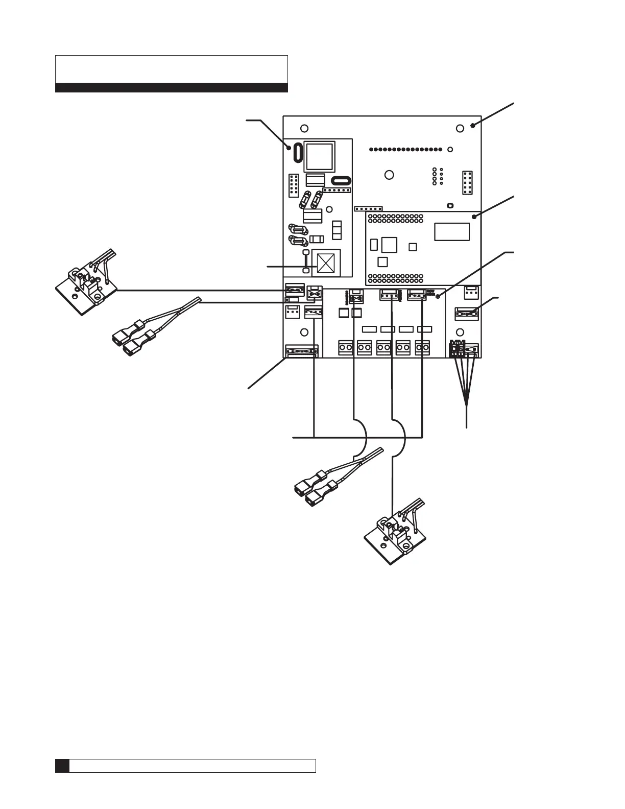
Blocking Solenoid Valve For External Blocking Multi-tank Operation
NOTE The solenoid valve is required only for multiple unit alternating or progressive flow systems.
Multi-Tank systems use communication cables (P/N 01024363). A Duplex system will
need 2 communication cables and a Triplex system will need 3 communication cables.
The communication cable should be used with the diaphragm valves of your choice,
such as the 1.5” plastic diaphragm valve (P/N 00445981).
Figure 35 illustrates the sequence of operation. Each valve in the system will require its
own solenoid valve and blocking valve. These solenoids are tubed as follows:
• From solenoid valve port number 1 to blocking valve port in head.
• From solenoid valve port number 2 teed into a pressurized source of water from
feed line.
• From solenoid valve port number 3 to a drain.
Figure 33. Solenoid Valve.