8 Culligan® High Efficiency 1.5 Water Softener
8 Cat. No. 01023552
Install Piping
1. Depending on the type of softener system (such as single, duplex, or triplex) and the installation parameters,
required pipe lengths and piping accessories will vary. See “Performance Specifications” on page 3 to aid
the installation. If the layout drawings are not sufficient for your application, consult the Culligan dealer for spe-
cific installation guidelines.
NOTE The use of unions and inlet and outlet isolation valves is recommended to facilitate the servicing of the
system. It is also recommended a full flow by-pass line be provided.
CAUTION! All soldering MUST be done on any connections requiring soldering prior to connect-
ing the main control valve. The main control valve will be damaged if it is connected at
the time of soldering.
2. Follow good plumbing practices for installation. These include:
a. Check threads and make certain that they are clean and free of foreign matter.
b. Fittings must be free of cracks or chips.
c. Prepare threads with either a pipe dope sealant or Teflon tape.
d. Make certain that the fittings are not cross threaded during the assembly process.
e. Do not over-tighten fitting or threaded pipe being inserted into a cast or forged part.
CAUTION! Never connect two dissimilar metals (such as copper and steel) together. The use of
dielectric unions or schedule 80 PVC or PVC plastic to break the connection is highly
recommended in order to reduce the risk of galvanic reaction and subsequent corrosion.
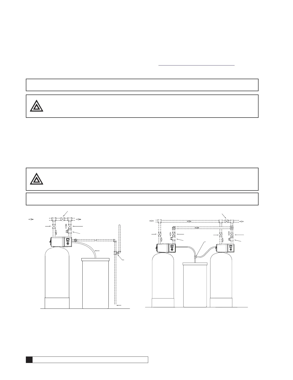
NOTE Figure 5 displays externally blocked progressive flow. Internally blocked progressive flow is plumbed
similarly but without the blocking valves.
SOFT WATER
MANUAL
OUTLET VALVE
BYPASS VALVE
(NORMALLY CLOSED)
HARD WATER
MANUAL
INLET VALVE
BRINE LINE
0.5"
DRAIN GAP
4" MIN.
SIPHON
BREAK
DRAIN LINE 3/4" OR 1"
VACUUM
BREAKER
Figure 4. Single tank vacuum breaker location.
WATER
DUPLEX TEE
HARD WATER
MANUAL
OUTLET VALVE
BYPASS VALVE
(NORMALLY CLOSED)
MANUAL
INLET VALVE
VACUUM
BREAKER
VACUUM
MANUAL
INLET VALVE
MANUAL
OUTLET VALVE
Figure 5. Duplex tank vacuum breaker location.