Installation 9
Cat. No. 01023552
CAUTION! The media tank must never be subjected to an internal vacuum or it might be dam-
aged. Drain line suction can be prevented by piping the system. A vacuum breaker
may be installed on either the inlet or the outlet side of the vessel as close to the ves-
sel as possible, preferably between the vessel and any isolating valves. If an installa-
tion has a booster pump downstream of the vessel, install the vacuum breaker on the
outlet side. Do not install a vacuum breaker on the drain line. Use a vacuum breaker,
such as Culligan P/N 00401584 or P/N 01003701. Multi-tank systems will require at
least one vacuum breaker per tank.
Suggested Piping Installations
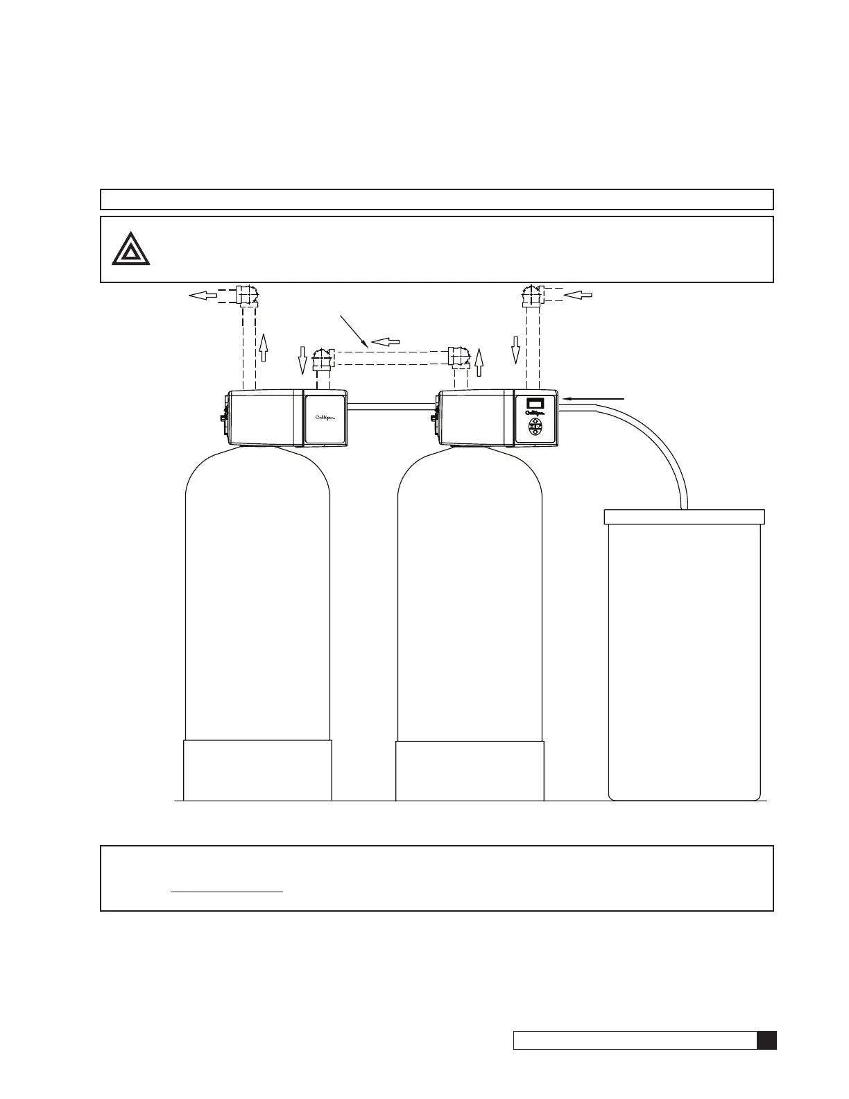
The piping layouts below depict a traditional three-valve bypass. Culligan also offers an optional bypass valve that con-
nects directly to the inlet and outlet of the water softener.
NOTE Interconnecting pipe and fittings, bypass valves, and isolation valves are not supplied.
NOTE Figure 7 displays externally blocked progressive flow. Internally blocked progressive flow is plumbed
similarly but without the blocking valves.
CAUTION! DO NOT make a direct connection to the drain. Provide an air gap of at least four times
the diameter of the drain pipe or conform to local sanitation codes and to permit the
observation of drain flow.
SOFT WATER
MANUAL
OUTLET VALVE
BYPASS VALVE
(NORMALLY CLOSED)
HARD WATER
MANUAL
INLET VALVE
0.5"
VACUUM
BREAKER
SMART
CONTROLLER
Figure 6. HE 1.5 single tank piping.
SMART CONTROLLER
WATER
HARD WATER
MANUAL
OUTLET VALVE
BYPASS VALVE
(NORMALLY CLOSED)
MANUAL
INLET VALVE
VACUUM
BREAKER
High Efficiency Twin
Figure 7. HE 1.5 duplex alternating tank piping.