M1 RO Installation 19
Cat. No. 01022940
Electrical Installation
WARNING! The system must be grounded. Do not remove grounding prong! An improperly
grounded unit could cause injury from electrical shock!
CAUTION! Observe the cautions listed below before the electrical installation of the controller.
Failure to do so might cause permanent damage to the RO controller.
CAUTION! Before performing any electrical wiring refer to the electrical schematics.
WARNING! Disconnect ALL power supplies when performing any electrical wiring.
A 120 VAC/60 Hz/1 phase grounded electrical receptacle with 15 Amp fuse protection is required for use with the six-foot,
three-wire power cord..
Pre-Installation Recommendations
• Follow the local electrical code requirements.
• Be sure electrical power is off and disconnected at the source before completing any wiring/cabling connections.
• Maintain a distance of at least 10 feet between the controller and any electrical distribution panels, raceways carry-
ing 300 volts or more.
• Use the cabling provided. Failure to do so may affect performance of the controller adversely.
High Voltage Connections
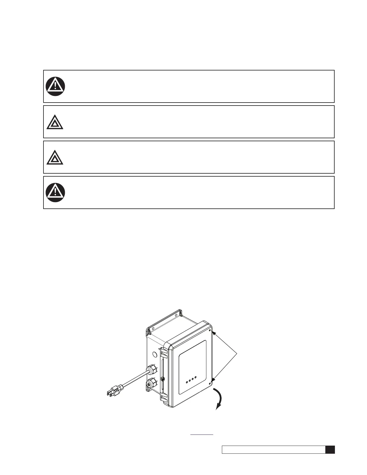
To open the control panel, unscrew the door screws in the counter clock-wise direction and swing the door open.
Door Screws
Swing Door Open
Figure 17. M1 control panel door.
The high voltage terminal strip is located on the circuit board (Figure 18). This terminal strip is prewired to the power cord,
motor power cord and the solenoid valve.

 Loading...


