M1 RO Parts Diagrams and Lists 51
Cat. No. 01022940
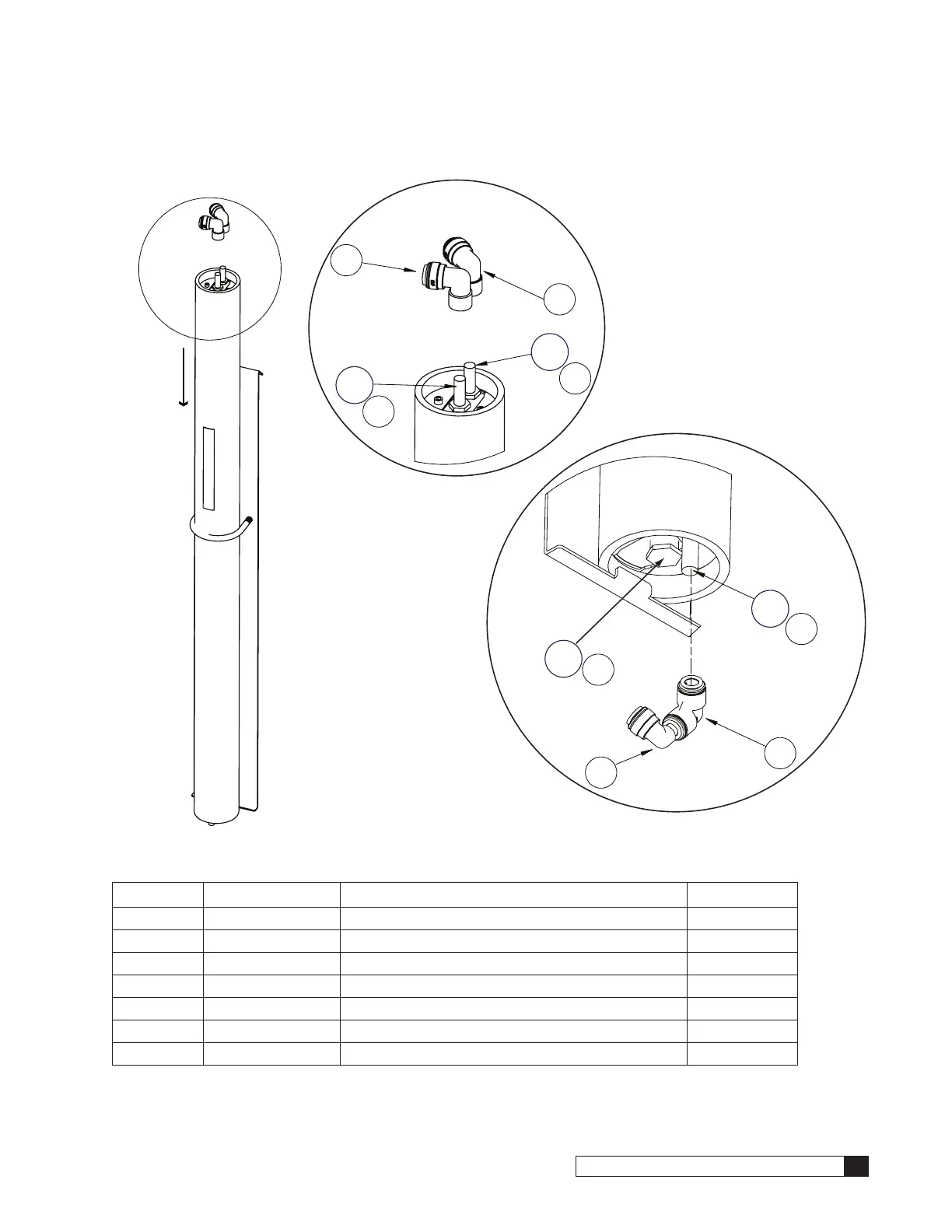
1S Sub-Assembly
Top View
Bottom View
A = to Feed Port
B = to Recirculating Assy
C = to Center Port (Product)
A
3
1
2
4
B
C
2
Note
Direction
of Flow
FEED
PRODUCT
5
C
2
3
Figure 33. M1-1S sub-assembly.
Item Part No. Description Quantity
01023412 Assembly, Membrane, Single, 2.5"x21"
01023904 Kit, Tube and Fittings, 1S (includes items 1–5)
1 — Elbow, Union, 3/8 Tube, PI, Polypropylene 1 EA
2 — Fitting, Stem Adapter, 1/4Tx3/8 Stem, Polypropylene 3 EA
3 — Elbow, Union, Reducing, 1/2 x 3/8, PI, Polypropylene 2 EA
4 — Fitting, Stem Elbow, 3/8T x 3/8 Stem, Polypropylene 3 EA
5 — Plug, 1/4" NPT, PVC Sch 80 1 EA

 Loading...


