Do you have a question about the Curt Manufacturing 58963 and is the answer not in the manual?
Behind driver side taillight housing for wiring.
Behind passenger side taillight housing for wiring.
Behind driver side rear access panel for wiring.
Behind passenger side rear access panel for wiring.
Behind driver side rear bumper for wiring.
Behind center of rear bumper for wiring.
Behind passenger side rear bumper for wiring.
Under rear floor panel for wiring.
Locate vehicle battery, disconnect negative terminal, and secure wire away from battery.
Loosen screws securing taillight with Torx T-27, remove taillight, and separate connectors.
Run fish wire from body to bumper cover, attach yellow wire to fish wire, and pull harness up.
Guide fish wire through blind hole, secure harness with tape, and pull wire back through.
Insert custom harness into factory wiring, ensure connectors are secure, and reinstall taillight.
Route green wire harness along bumper backside to passenger side, securing with cable ties.
Locate grounding point, clean area, and secure white ground wire with terminal.
Route 4-flat wire between rear drive line mounts and body, zip tie securely away from hazards.
Locate plastic skid plate, remove bolts and nut to access area.
Route 4-flat wire under skid plate and along brake lines to the front tire.
Use fish wire to route 4-flat from inner fender to engine compartment.
Route 4-flat along driver side outer fender, under mounts and shroud, to core support.
Secure excess wire, tighten zip ties, reinstall items, and reconnect battery terminal.
Lists necessary tools for installation, including sockets, ratchet, and fish wire.
Periodic inspection of wires and connections for damage or looseness.
Information on product registration and warranty through CURT Group.
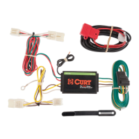
This document outlines the installation and maintenance procedures for a custom wiring harness designed to provide trailer lighting functionality for SUVs and vans. The harness is intended to be integrated with the vehicle's existing electrical system to ensure proper operation of trailer lights, including taillights, brake lights, and turn signals.
The primary function of this device is to enable a vehicle to safely and effectively tow a trailer by providing the necessary electrical connections for trailer lighting. It acts as an intermediary between the tow vehicle's lighting system and the trailer's lighting system, ensuring that signals from the vehicle's taillights, brake lights, and turn signals are accurately transmitted to the corresponding lights on the trailer. This is crucial for road safety, as it makes the trailer's presence and intended maneuvers visible to other drivers. The harness is designed to be a "4-flat" system, which is a common standard for basic trailer lighting, typically covering running lights, left turn/brake, right turn/brake, and ground.
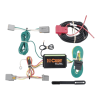
The installation process involves routing the harness from the rear of the vehicle, where it connects to the taillight assemblies, all the way to the front engine compartment. This comprehensive routing ensures that the harness is securely integrated and protected within the vehicle's chassis, minimizing exposure to external elements and potential damage. The system is designed to be compatible with the vehicle's existing wiring, utilizing factory connectors where possible to simplify installation and maintain the integrity of the vehicle's electrical system.
A key aspect of the harness's functionality is its ability to draw power and signals from the vehicle's existing lighting circuits without overloading them. It is imperative to adhere to the product's rating and the tow vehicle's lamp load rating to prevent electrical issues. The harness is engineered to provide a reliable and consistent electrical connection, which is essential for the safe operation of a trailer, especially during night driving or in adverse weather conditions.
The wiring harness is designed for ease of use once installed. The "4-flat" connector, typically located at the rear of the vehicle, provides a straightforward connection point for a trailer. Users simply plug the trailer's 4-flat connector into the vehicle's harness connector. The system is designed to automatically mirror the vehicle's lighting functions, meaning that when the vehicle's headlights are on, the trailer's running lights will activate; when the brake pedal is pressed, the trailer's brake lights will illuminate; and when the turn signal is engaged, the corresponding trailer turn signal will flash.
The installation guide emphasizes the importance of proper routing and securing of the wires to prevent damage and ensure longevity. This includes keeping the wiring away from hot spots, pinch points, and moving objects within the vehicle's undercarriage and engine bay. The use of cable ties, as recommended in the instructions, is crucial for maintaining a tidy and secure installation, which in turn contributes to the reliability of the system.
The harness also features a grounding point, which is a critical component for any electrical system. A secure and clean ground connection ensures proper current flow and prevents electrical malfunctions. The instructions detail how to prepare the grounding surface by removing rust, dirt, and paint, ensuring an optimal connection.
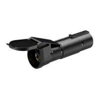
For added protection and longevity, a 4-flat dust cover is provided. This cover should be installed on the connector when it is not in use to protect it from dirt, moisture, and debris, which can otherwise lead to corrosion and poor electrical contact over time. This simple feature helps maintain the integrity of the connection point, ensuring reliable performance whenever a trailer is connected.
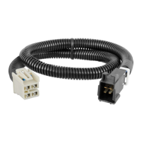
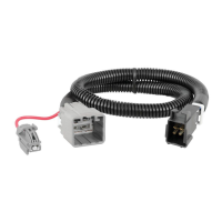
The system is designed to be an add-on, allowing the vehicle's RV harness to also function as a trailer light harness. This versatility means that the vehicle can be used for various towing needs without requiring separate wiring solutions for different types of trailers that utilize a 4-flat connection.
The maintenance requirements for this wiring harness are minimal but crucial for ensuring its long-term reliability and safe operation. The primary maintenance feature is periodic inspection. Users are advised to regularly inspect all wires and connections to ensure there is no visible damage or loose connections. This proactive approach can help identify potential issues before they lead to system failure or safety hazards.
During these inspections, users should look for signs of wear and tear, such as frayed wires, cracked insulation, or corroded terminals. Any loose connections should be tightened, and damaged wires should be repaired or replaced as necessary. The instructions emphasize securing any excess wire with zip ties during installation, and this practice should be maintained over time to prevent wires from drooping or dangling, which could expose them to damage from road debris, moving vehicle components, or environmental factors.
The 4-flat dust cover, provided with the harness, plays a significant role in maintenance. By consistently using this cover when the connector is not in use, users can prevent the accumulation of dirt, moisture, and road salt, all of which can cause corrosion on the electrical terminals. Corrosion can lead to poor electrical contact, intermittent lighting, or complete system failure. Regularly cleaning the connector terminals, especially if they are exposed to harsh conditions, can also extend the life of the harness.
The grounding point, a critical component of the electrical circuit, should also be periodically checked. While the initial installation requires preparing a clean, rust-free surface, environmental factors can lead to corrosion over time. Ensuring the ground connection remains secure and free of corrosion is vital for the entire system's performance.
In summary, the maintenance of this wiring harness primarily involves visual inspections, ensuring secure connections, protecting the connector from environmental damage with the provided dust cover, and addressing any signs of wear or corrosion promptly. Adhering to these simple maintenance practices will help ensure that the trailer lighting system remains functional and safe for many years of towing.
| Material | Steel |
|---|---|
| Brand | Curt Manufacturing |
| Part Number | 58963 |
| Category | Automobile Accessories |
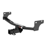
| Receiver Size | 2" |
| Product Type | Hitch |
| Finish | Black |
| Hitch Type | Receiver |
| Warranty | Limited Lifetime |