PAGE 3
•
51190-INS-RC
•
87 7.2 87.86 34
•
NEED ASSISTANCE?
•
CURTMFG.COM
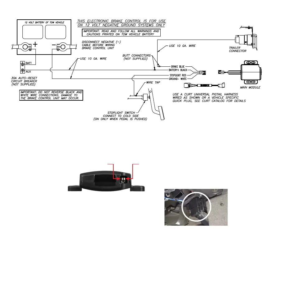
WIRING DIAGRAM
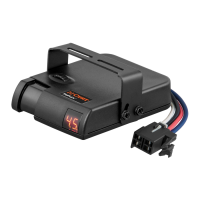
SET MANUAL CONTROL OUTPUT
AND BRAKE LIGHT SWITCHES
There are two small
switches located at the
front of the unit, next to
the port on the module.
Once accessed, the switch
positions can be changed
using a small pointed tool.
In the illustration above, the switch on the left (#1) controls the
unit's brake light activation feature. The factory default setting is
the 'ON' position with the switch down. This setting activates the
tow vehicle and trailer brake lights when the manual control is
actuated. Moving the switch up to the 'OFF' position turns off the
brake light activation feature and the brake lights are not activated
when the manual control is actuated.
In the illustration above, the switch on the right (#2) controls
the level of output available to the trailer brakes when using the
manual control. The factory default setting is the 'ON' position with
the switch down. This setting limits the manual control output to
the level set using the output control. Moving this switch up to the
'OFF' position allows 100% of the output to the brakes when the
manual control is actuated regardless of the output control setting.
2
1
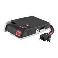
1. Once the CURT quick connector or splice-in harness is installed,
determine a suitable mounting location for the module.
a. The module must be mounted securely to a solid surface
under the dash. The orientation of the module does not matter.
b. This module should be easy to access for troubleshooting.
It can be installed out of sight to reduce contact with operator.
MOUNTING THE MODULE
2. See the 'Set Manual Control Output and Brake Light Switches'
section in the previous section before mounting the module.
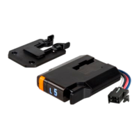
3. Secure the module in place using the
provided adhesive pad and zip-ties.
4. Plug in the module to the pigtail harness
or vehicle-specific quick plug. If harness is
unavailable, hard wiring will be necessary.
Figure 1