Do you have a question about the curt DISCOVERY 51126 and is the answer not in the manual?
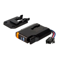
Identifies the main unit, mounting bracket, screws, adhesive, and cable ties.
Lists necessary tools like drill, bits, screwdriver, and pry tool.
Lists necessary harnesses and wiring kits for brake controller installation.
Provides crucial safety advice and installation precautions before starting.
Selects between custom vehicle or universal splice-in harnesses.
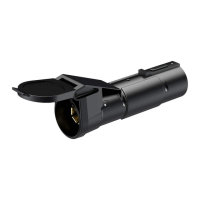
Guides locating the vehicle plug and routing the wiring harness.
Verifies clearance and plugs the harness into the controller.
Illustrates connections to the vehicle battery and ground points.
Details wiring for the stoplight switch and trailer brake signal.
Identifies a suitable, accessible, and clear mounting spot in the vehicle.
Guides marking, drilling, and securing the mounting bracket.
Slides the brake controller onto the mounted bracket until it clicks.
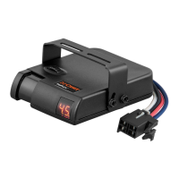
Describes manual override, auto output, gain, load, and brightness modes.
Explains indicators for calibration, overload, low voltage, shorts, and connection status.
How to change the LED display brightness using rocker switches.
Instructions for toggling between day and night display modes.
Explains how the manual control applies trailer brakes for speed reduction.
Shows how the LED display reflects output proportional to manual lever pressure.
Sets the maximum power available to the trailer brakes via rocker switches.
Details using rocker switches to increase/decrease gain.
Shows trailer brake output during normal braking based on settings.
Controls trailer brake aggressiveness using the right rocker switch.
Explains signals for overload, electrical shorts, and low voltage conditions.
Details indicators for connected, not connected, and start-up status.
Steps for connecting the trailer and allowing the controller to sense it.
Describes controller behavior when the vehicle starts or restarts.
Methods to recalibrate the brake controller if needed.
Initial adjustments for gain and load with trailer connected.
How to adjust gain for smooth stops without trailer tire lock-up.
How to adjust load for desired aggressiveness and smooth stops.
Reminder to repeat adjustments for changing weather or load conditions.
Lists materials needed for testing the controller independently of a vehicle.
Instructions for connecting components for testing and safety precautions.
Adjusts controller settings to their highest levels for testing.
Operates manual control to verify output and bulb illumination.
Addresses issues where the display remains blank during operation.
Troubleshoots when the controller indicates no trailer connection.
Identifies and resolves low voltage issues affecting the controller.
Diagnoses and corrects electrical short circuit conditions.
Guides troubleshooting for overload conditions in the brake system.
Addresses lack of display power when the engine is not cranked.
Resolves 'not connected' display when a trailer is attached.
Fixes issues where trailer brakes fail due to shorts or overloads.
Addresses errors when trailer brakes function but display shows fault.
Troubleshoots lack of trailer braking due to electrical connection issues.
Resolves no trailer brakes caused by unplugged or faulty trailer connections.
Details how to access product warranties and register purchases.
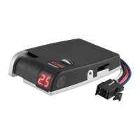
The CURT Discovery™ Next Brake Controller (model 51126) is an electronic device designed to manage trailer brakes, ensuring smooth and firm stops. It is suitable for use with 12-volt negative ground systems.
The brake controller activates trailer brakes proportionally to the pressure applied to the manual control or vehicle brake pedal. It allows for adjustments to both "gain" (maximum power to trailer brakes) and "load sensitivity" (trailer brake aggressiveness) to suit individual driver preferences, trailer load changes, and varying road conditions. The device features an LED display that shows output settings, operational modes, and indicator sequences, aiding in setup, monitoring, and troubleshooting.
| Brand | curt |
|---|---|
| Model | DISCOVERY 51126 |
| Category | Controller |
| Language | English |