EasyManua.ls Logo

Curtis Instruments F Series User Manual

Curtis Instruments F Series
214 pages
To Next Page IconTo Next Page
To Previous Page IconTo Previous Page
Page #13 background image
2 — INSTALLATION AND WIRING
pg. 5
Return to TOC Curtis AC F4-A Motor Controller – August 2020
e high power connections are aluminum M6 terminals. Terminate the battery and motor cables
with high quality (tin-plated) copper lugs to match the application. Ensure the M6 bolts are the
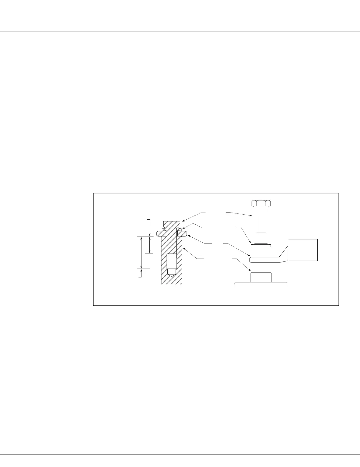
proper length to meet the minimum thread depth engagement. Do not bottom-out the bolts in any
terminal. Follow Figure 3 connection guidelines:
Place the lug on top of the aluminum terminal, followed by a high-load safety washer with its
convex side on top. e washer should be a SCHNORR 416320, or equivalent.
For terminal connections with more than one lug, stack them so the lug carrying the least
current is on top.
Ensure the clamping bolt is within the minimum and maximum depth when assembled.
Tighten the assembly to 10.2 ±1.1 Nm (90 ±10 in-lbs.).
When routing the battery cables between the battery and controller, run the positive and negative
battery cables close to each other, avoiding pinch-points and areas of possible cable abrasion.
Typically, the positive cable is red and the negative cable is black. e motor phase cables are oen
black, yet clearly labeled at both ends. Reference Appendix B, Vehicle Design Considerations for
EMC guidelines.
Figure 3
Battery Power
and Motor
Phase Terminal
Connections
M6 BOLT
HIGH LOAD
SAFETY WASHER
LUG
M6 TERMINAL
SECTION VIEW
F4-A TERMINALS
EXPLODED VIEW
10 mm MIN
DEPTH
18 mm
MAX
DEPTH

Table of Contents

Question and Answer IconNeed help?

Do you have a question about the Curtis Instruments F Series and is the answer not in the manual?

Curtis Instruments F Series Specifications

General IconGeneral
BrandCurtis Instruments
ModelF Series
CategoryController
LanguageEnglish

Summary

OVERVIEW

HOW TO USE THIS MANUAL

Explains how to navigate and utilize the manual's content for understanding the controller.

GETTING THE MOST OUT OF YOUR CURTIS CONTROLLER

Provides guidance on applying and configuring the F4-A controller for optimal performance.

INSTALLATION AND WIRING

PHYSICALLY MOUNTING THE CONTROLLER

Details the process for properly mounting the controller to ensure environmental protection and optimal heat dissipation.

PRECAUTIONS

Outlines essential safety measures and EMC mitigation design considerations for controller installation.

HIGH CURRENT CONNECTIONS

Describes the connections for battery and motor phase terminals, including fuse and contactor requirements.

LOW CURRENT CONNECTIONS

Explains the use of the 35-pin AMPSEAL connector for logic and low-power signals, including component part numbers.

CONTROLLER INPUTS AND OUTPUTS

Lists available Inputs and Outputs (I/O) types, detailing their function and pin assignments.

CONTROLLER WIRING DIAGRAM (EXAMPLES)

Illustrates typical wiring configurations for various inputs, outputs, and CAN ports.

DIGITAL (SWITCH) INPUTS

Describes the controller's digital input configurations and their specifications for switch interfacing.

ANALOG INPUTS

Details the controller's support for various analog inputs and their allowable voltage ranges.

POTENTIOMETER INPUTS WITH DYNAMIC TESTING

Explains the use of potentiometer inputs for throttles and their internal fault detection circuits.

PWM AND DIGITAL DRIVERS

Describes the low-side PWM drivers and digital drivers for loads like coils and LEDs, including their electrical specifications.

POWER SUPPLY OUTPUTS

Details the 5-volt and 12-volt power supplies providing auxiliary power for low-power circuits.

KEYSWITCH AND COIL SUPPLY

Explains the connection of the keyswitch input and coil supply circuits for controller power and precharge.

CAN PORTS

Describes the two available CAN ports, their configurations, and supported protocols for communication.

MOTOR POSITION SENSOR INPUTS

Details the inputs for AC induction and synchronous motors, supporting quadrature encoders and Sine/Cosine sensors.

MOTOR TEMPERATURE INPUT

Explains the motor temperature sensor input that measures resistance for controller support.

APPLICATION-SPECIFIC FEATURES

MOTOR SPEED CONSTRAINTS

Explains how motor poles, encoder pulses, and Max Speed parameter limit the maximum motor speed.

VOLTAGE LIMITS

Describes the hardware and parameter-based voltage limits that protect the system from over/under voltage conditions.

BROWNOUT VOLTAGE

Defines the fixed brownout voltage region where the controller bridge is switched off.

PROGRAMMABLE PARAMETERS

PROGRAMMING MENUS

Groups programmable parameters into nested hierarchical menus, detailing each parameter and its operation.

PARAMETER CHANGE FAULTS [PCF]

Explains faults triggered when parameters are changed while the motor bridge is enabled.

PROGRAMMING TOOLS

Lists the tools used for programming, including PC-based CIT and the 1313 handheld programmer.

MENU CHART FORMAT

Describes how each parameter is presented in a detailed chart, including display name, allowable range, and description.

TERMINOLOGY

Provides definitions for terms used in setting parameters and commissioning the vehicle.

Speed Mode Express Parameter menus

Introduces a simplified version of Speed Mode with fewer parameters for speed-controlled applications.

Speed Mode Parameter menus

Offers comprehensive motor response parameters and tuning options for speed control.

SYSTEM MONITOR MENU

INPUTS MENU

Displays the status of all controller inputs, including analog and digital signals.

OUTPUTS MENU

Shows the status of controller outputs, including PWM and driver current values.

CURRENT LIMITS MENU

Sets parameters for drive, regen, brake, and EMR current limits as a percentage of controller rating.

CONTROLLER MENU

Displays real-time controller status, including current, temperature, and operational states.

BATTERY MENU

Shows battery status variables such as BDI, keyswitch voltage, and battery current.

COMMISSIONING

INITIAL SETUP

Outlines essential initial setup steps to ensure controller settings match the application.

TRACTION MOTOR SELECTION

Guides on determining correct motor parameters like Motor Type and Field Weakening.

ACIM MOTOR SETUP

Provides setup guidance specific to AC Induction Motors (ACIM).

Tuning Guide

Offers procedures for tuning vehicle performance after initial setup.

Setting Up the Hydraulic System

Provides procedures for setting up hydraulic systems, including lift and lower commands.

DIAGNOSTICS AND TROUBLESHOOTING

THE DIAGNOSTICS PROCESS

Explains how to obtain diagnostics information via status indicator, programmer, or CAN messages.

TROUBLESHOOTING CHART INDEX

Provides an index of flash codes, fault names, CAN indexes, and corresponding pages for troubleshooting.

FAULT ACTIONS

Describes the specific actions taken by the controller when a fault is detected, based on action codes.

MAINTENANCE

CLEANING

Provides routine cleaning procedures for the controller exterior to prevent corrosion.

FAULT HISTORY

Explains how to access and clear the controller’s fault history file using programming tools.

APPENDIX A

CAN PDO MAP SETUP

Provides guidance on setting up PDO maps using the Curtis Integrated Toolkit for F-series controllers.

APPENDIX B

ELECTROMAGNETIC COMPATIBILITY (EMC)

Discusses emissions and immunity standards and techniques to reduce EMC problems.

DECOMMISSIONING AND RECYCLING THE CONTROLLER

Outlines procedures for controller decommissioning and recycling according to OEM and landfill regulations.

APPENDIX C

EN 13849 COMPLIANCE

Explains compliance requirements for Safety Related Parts of Control Systems under EN13849.

APPENDIX D

PROGRAMMING, MONITORING, and DIAGNOSTIC SOFTWARE

Summarizes programming tools like CIT and 1313 HHP, and their applications.

CURTIS INTEGRATED TOOLKITTM

Describes the CIT software for configuring and communicating with Curtis products.

CREATING A PROJECT WITH A NEW F-SERIES CONTROLLER

Guides on creating new projects within the CIT software for controller setup.

VEHICLE CAN-PORT WIRING

Details the installation of the vehicle CAN port and its wiring specifications.

APPENDIX E

SPECIFICATIONS: CONTROLLER

Provides detailed electrical and mechanical specifications for the AC F4-A Controller.

Related product manuals