4 — PROGRAMMABLE PARAMETERS
pg. 87
Return to TOC Curtis AC F4-A Motor Controller – August 2020
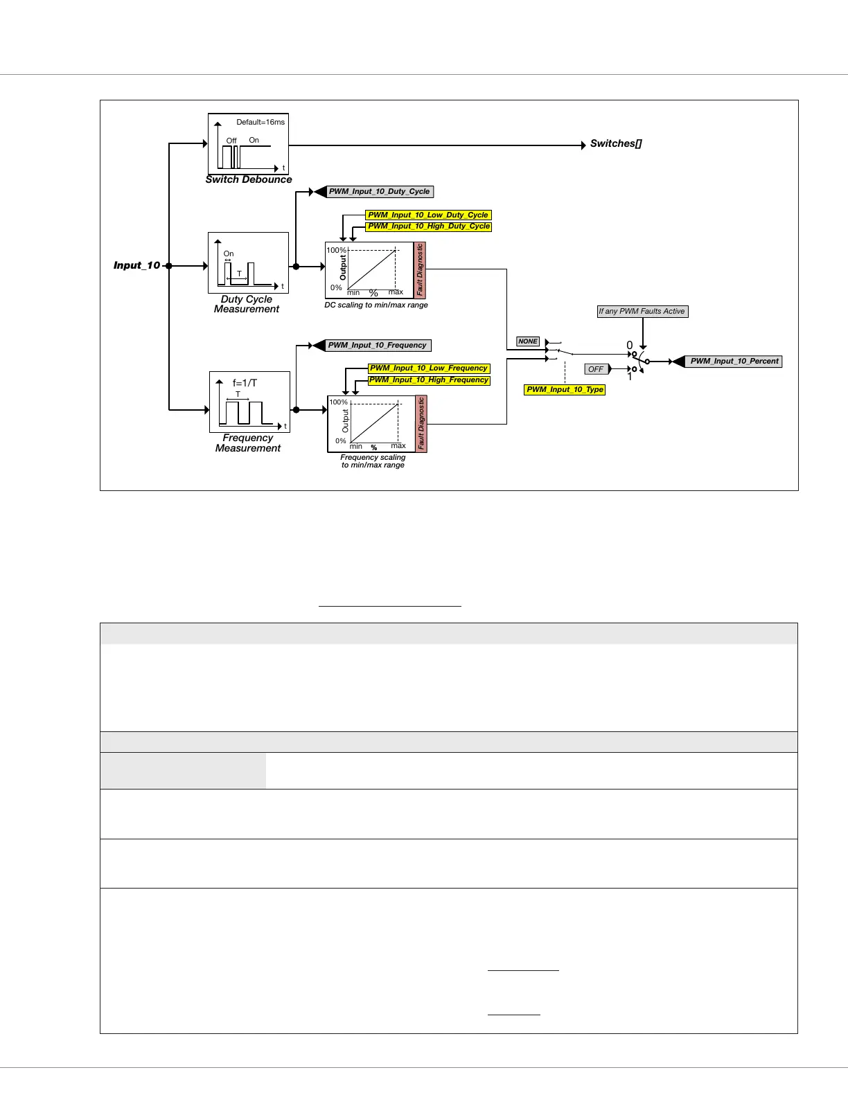
DC scaling to min/max range
PWM_Input_10_Low_Duty_Cycle
Frequency scaling
to min/max range
PWM_Input_10_Low_Frequency
PWM_Input_10_High_Duty_Cycle
PWM_Input_10_High_Frequency
Figure 21
Input 10 Digital and Analog Signal Chain
CONTROLLER SETUP — INPUTS MENU
PARAMETER ALLOWABLE RANGE DEFAULT DESCRIPTION
Analog 1 Type
Analog_Input_1_Type
0x32E6 0x00
Enumeration
0 – 3
Voltage Congure the Analog1 input by throttle or load type.
0 – Voltage (Hall-effect or voltage throttle)
1 – 3-Wire Pot Wiper (3-wire resistive potentiometer throttle)
2 – 2-Wire Pot Wiper (2-wire resistive potentiometer throttle)
3 – Voltage with Supply (a non-throttle load alternative)
Analog 1 menu
Parameters for Voltage
selection
Reference the Voltage Throttle section, Chapter 6
Analog 1 Type
Analog_Input_1_Type
0x32E6 0x00
Voltage
(selection menu)
– Selecting the Voltage option opens the menu to its corresponding
monitor variables and the low/high parameters.
Voltage
Analog_Input_Volts_1
0x3B2E 0x00
–327.68 – 327.67
–32768 – 32767
Read Only
V
The analog voltage at the input pin 16.
Percent
Analog_Input_Percent_1
0x3B39 0x00
0.0 – 100.0 %
0 – 1000
Read Only
%
The percentage of the voltage at pin 16 based upon the High and
Low settings, i.e., the percent of:
((analog_input_volts_1) – (analog_input_1_low)) /
((analog_input_1_high – (analog_input_1_low))
Voltage Throttle usage: reference the Forward Min/Max & Reverse
Min/Max Input parameters located in the Application Setup »
Throttle menu.
Brake input usage: reference the Brake Min/Max Input
parameters located in the Application Setup » Brake menu.