Curtis 1352 eXm Manual, R ev. D
7
2 — INSTALLATION & WIRING: Low Current Connections
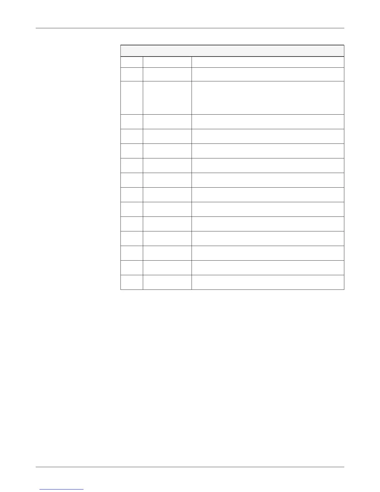
Table 1 Connector Pinout
pin name description
1 B– Ground; connected to battery B– terminal.
2 B– Redundant ground, for high-current applications.
If the combined draws from the driver pins could exceed
9A, both B– pins must be connected to the battery’s B–
terminal
3 B+ Power; connected to the battery’s B+ terminal.
4 CAN L CAN bus Low communication line.
5 CAN H CAN bus High communication line.
6 Analog Input 1 Voltage or resistive input.
7 Analog Input 2 Voltage or resistive input.
8 Analog Input 3 Voltage input only.
9 Input/Output 5 Active High input & high-power PWM active Low output.
10 Input/Output 6 Active High input & high-power PWM active Low output.
11 Input/Output 1 Active High input & high-power PWM active Low output.
12 Input/Output 2 Active High input & high-power PWM active Low output.
13 Input/Output 3 Active High input & high-power PWM active Low output.
14 Input/Output 4 Active High input & high-power PWM active Low output.