8
Curtis 1352 eXm Manual, R ev. D
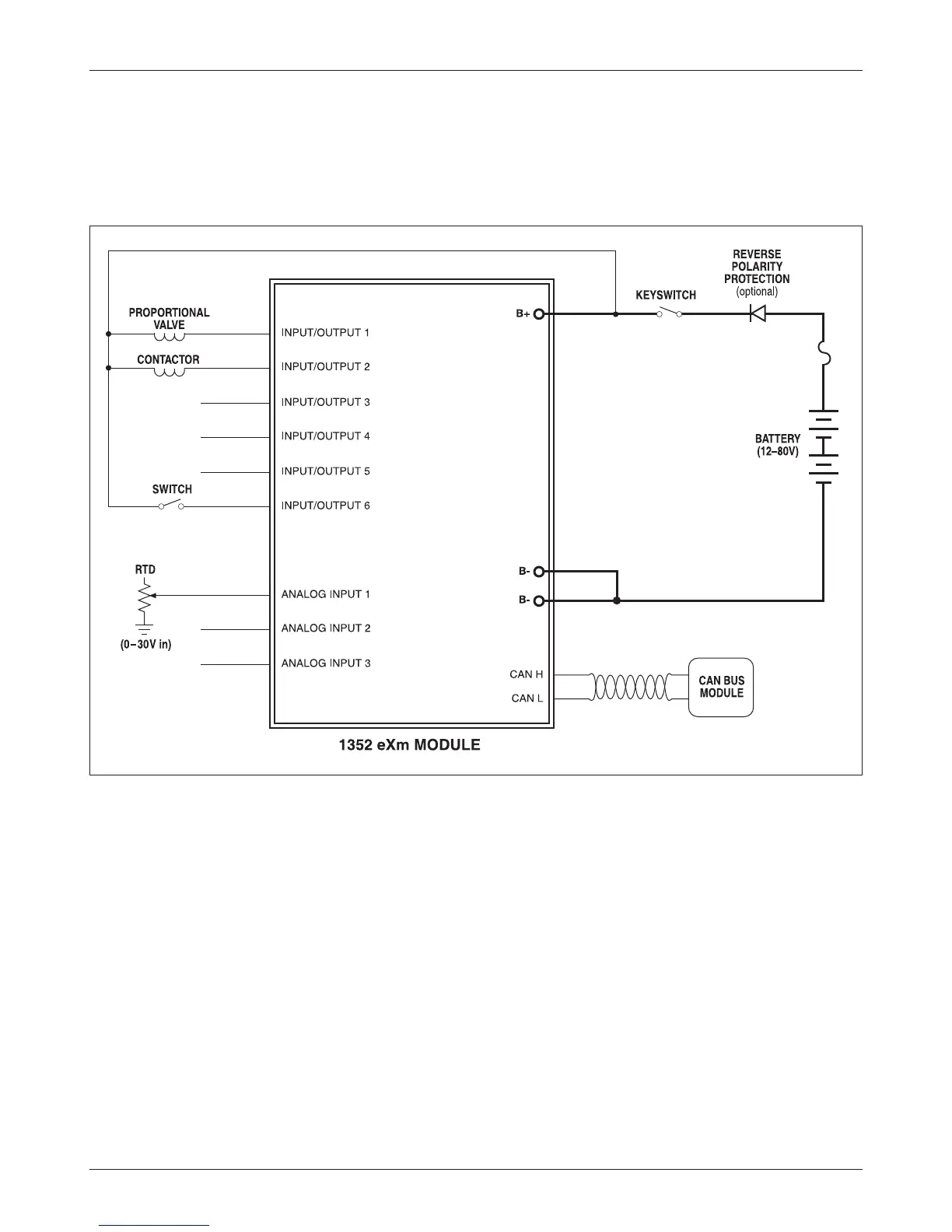
Fig. 3 Basic wiring diagram, Curtis 1352 eXm module.
2 — INSTALLATION & WIRING: Standard Wiring Diagram
WIRING: BASIC CONFIGURATION
A basic wiring diagram is shown in Figure 2, and described below. The diagram
shows shows the standard power and battery connections, as well as a variety
of basic uses for the inputs and outputs.
Power Connection
The battery is connected to the module’s B+ pin though a fuse, an optional
diode, and a keyswitch. The fuse protects the wiring in the event of a short or
failure. The return path of the coils is also brought back to the B+ pin to utilize
the flyback diodes connected inside the eXm between B+ and each driver output.
The keyswitch is used to turn on the system. When the keyswitch is closed,
B+ goes high and the eXm’s power supply brings up the module.
Outputs
All the drivers (Pins 9–14) are identical. Each is capable of driving a closed-loop
current-controlled proportional valve or a voltage-controlled contactor. Each
driver has independent mode, max, and dither settings.
Pin 5
Pin 4
Pin 2
Pin 1
Pin 3
Pin 11
Pin 12
Pin 13
Pin 14
Pin 9
Pin 10
Pin 6
Pin 7
Pin 8