4
Curtis 1352 eXm Manual, R ev. D
2 — INSTALLATION & WIRING
2
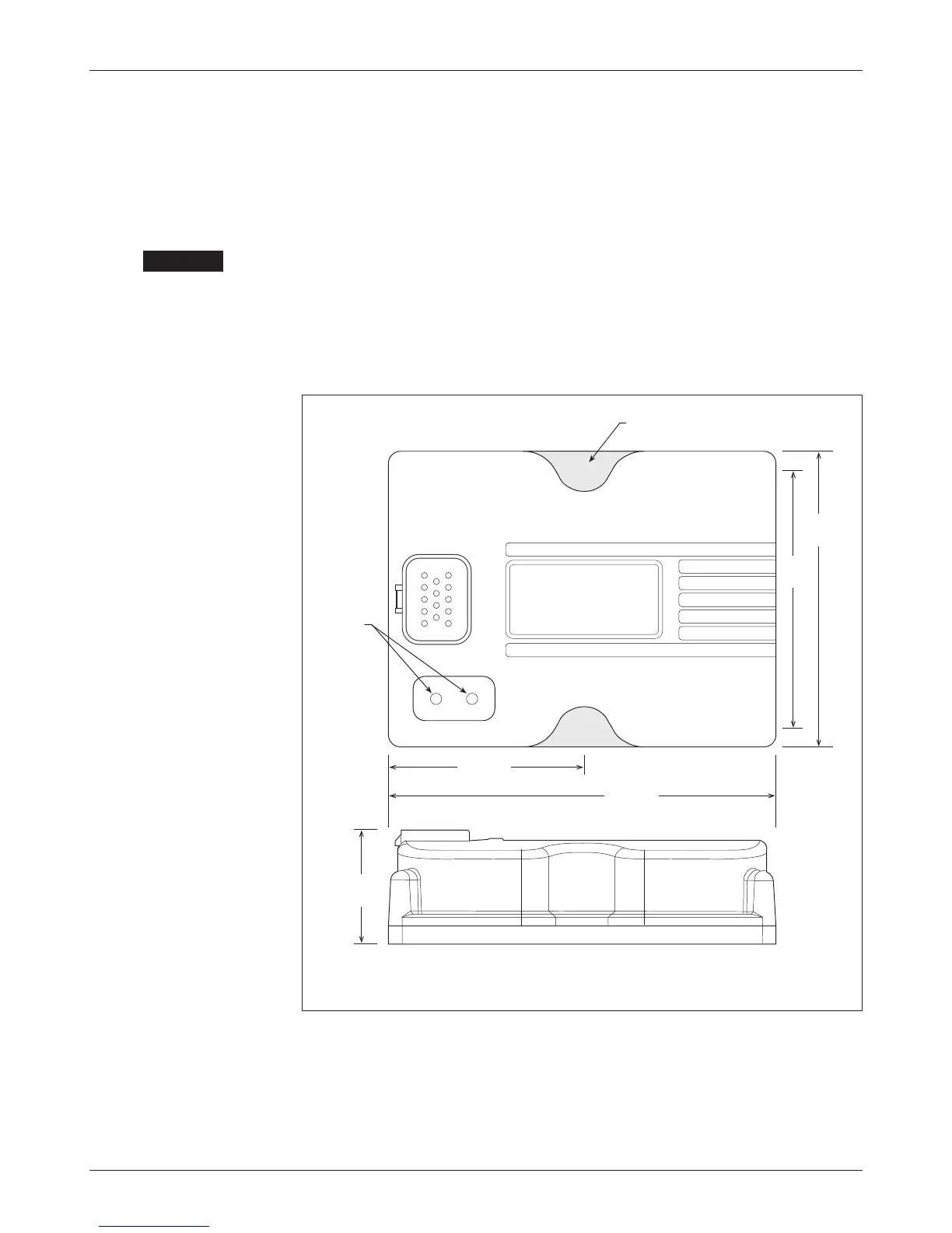
Fig. 2 Mounting
dimensions, Curtis 1352
eXm module.
Dimensions in millimeters (and inches)
INSTALLATION AND WIRING
MOUNTING THE MODULE
The outline and mounting hole dimensions for the 1352 eXm module are shown
in Figure 2. The module should be mounted using two #10 or M5 screws.
Care should be taken to prevent contaminating the connector area
before the mating 14-pin connector is installed. Once the system is plugged
together, the eXm meets the IP65 requirements for environmental protection
against dust and water. Nevertheless, in order to prevent external corrosion
and leakage paths from developing, the mounting location should be carefully
chosen to keep the module as clean and dry as possible.
If the outputs will be used at or near their maximum ratings, it is rec-
ommended that the module be mounted to a good heatsinking surface, such
as an aluminum plate.
65 (2.6)
130 (5.2)
Status
LEDs
100
(3.9)
87
(3.4)
6.3 (0.25) dia.,
2 plcs
39
(1.5)
+
CAUTION