EasyManua.ls Logo

Curtis 1353 User Manual

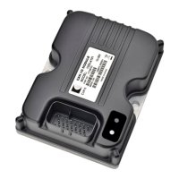
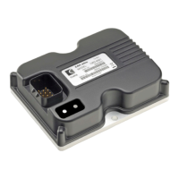
Curtis 1353
55 pages
To Next Page IconTo Next Page
Page #1 background imageLoading...
Page #1 background image
Manual
CANopen Expansion Module
Read Instructions Carefully!
Specications are subject to change without notice.
© 2017 Curtis Instruments, Inc. ® Curtis is a registered trademark of Curtis Instruments, Inc.
© The design and appearance of the products depicted herein are the copyright of Curtis Instruments, Inc. 53053, Rev F June 2017
Curtis Instruments, Inc.
200 Kisco Avenue
Mt. Kisco, NY 10549
www.curtisinstruments.com
Model 1353

Questions and Answers:

Curtis 1353 Specifications

General IconGeneral
BrandCurtis
Model1353
CategoryControl Unit
LanguageEnglish

Summary

1 - Overview

Descriptions of Key Features

Details the key features of the Curtis 1353 CANopen Expansion Module, covering outputs, dither, and current/voltage control.

Key Feature Details

2 - Installation and Wiring

Module Mounting Guidelines

Provides dimensions and recommendations for mounting the 1353 module, including screw types and heatsinking.

Connector Pinout and Wiring Recommendations

Details the 23-pin connector pinout and provides recommendations for wiring power, drivers, and CANbus.

Basic Wiring Configuration

Input/Output Signal Specifications

Driver Output Specifications

Details specifications for the nine driver outputs, including max current, impedance, and frequency characteristics.

3 - CANopen Communications

Minimum State Machine

Describes the CANopen minimum state machine, including states like Initialization, Pre-Operational, and Operational.

Baud Rates and CAN Node ID Configuration

Details selectable baud rates and methods for configuring the CAN Node ID using parameters and digital inputs.

NMT Messages and Device States

Explains Network Management Transmission (NMT) messages, their function in setting device states, and command specifiers.

Emergency and Heartbeat Messages

4 - PDO Communications

PDO Message Structure and Timing

Explains the four fixed PDO communication packets, their bus bandwidth conservation, and PDO timeout fault handling.

PDO1-MOSI and PDO2-MOSI Command Data

Details the data bytes for PDO1-MOSI (Output Commands) and PDO2-MOSI (Output 9 Command, BDI).

PDO1-MISO and PDO2-MISO Status Data

Details the data bytes for PDO1-MISO (Input Status, Virtual Digital Inputs) and PDO2-MISO (Analog Input Data, Encoder Data).

5 - SDO Communications

SDO Master Request (SDO-MOSI) Format

Details the 8-byte SDO request format, including control byte, object index, sub-index, and data transfer.

SDO 1353 Response (SDO-MISO) Format

Explains the SDO response format, including acknowledge codes, error codes, and how read/write values are returned.

Communication Profile Objects Dictionary

Store Parameter Object Functionality

Restore Default Parameters Object

Parameter Profile Objects Dictionary

Driver Proportional Gain / Driver Integral Gain

PI Controller Gains (Kp and Ki)

Explains the Proportional (Kp) and Integral (Ki) gains in the PI controller for adjusting responsiveness in Constant Current/Voltage modes.

5 - Monitor Objects

6 - Diagnostics and Troubleshooting

Fault Logging and Status LED Indicators

Explains how fault codes and timestamps are logged in a FIFO buffer and how status LEDs indicate faults.

Troubleshooting Chart: Fault Codes and Recovery

Introduces the troubleshooting chart that lists fault codes, descriptions, effects, and recovery procedures.

7 - Serial Communications & Programming

Program Menu Structure Overview

Introduces the hierarchical program menus for adjusting parameters, monitoring values, and accessing diagnostics.

Driver Output and CAN Interface Program Menus

Details parameters for Driver Outputs (Operation Mode, Current, Voltage, Dither, PI) and CAN Interface (Baud Rate, Node ID, Rates).

Appendix A: Design Considerations

Electromagnetic Compatibility (EMC) Principles

Discusses EMC principles, including emissions and immunity, and techniques to enhance performance in Curtis controller products.

Electrostatic Discharge (ESD) Protection Measures

Covers ESD-sensitive components, protection methods against discharge, and importance of proper grounding and insulation.

Appendix B: Programming Devices

PC Programming Station (1314) Capabilities

Describes the 1314 PC Programming Station software application for programming, diagnostics, and testing.

Handheld Programmer (1313) and Its Functions

Details the 1313 handheld programmer's equivalence to the PC station and its functions: parameter adjustment, monitoring, diagnostics, programming.

Appendix C: Specifications

1353 Module General Specifications Table

Lists general specifications for the 1353 module: input voltage, isolation, temperature ranges, enclosure, weight, and dimensions.

1353 Module Model-Specific Specifications Table

Details model-specific voltage ranges, serial port availability, and analog input counts for 1353-4001, -4101, -6001, -6101.

Related product manuals