2 — INSTALLATION AND WIRING
pg. 13
Return to TOC Curtis 1353 CANopen Expansion Module Manual – June 2017
Analog Inputs
e 1353 has four or six 0 – 15 V analog inputs, depending on the model. ese inputs are scaled
down by 5.76, clamped to 3.3 V, and read by a 12-bit ADC internal to the MCU.
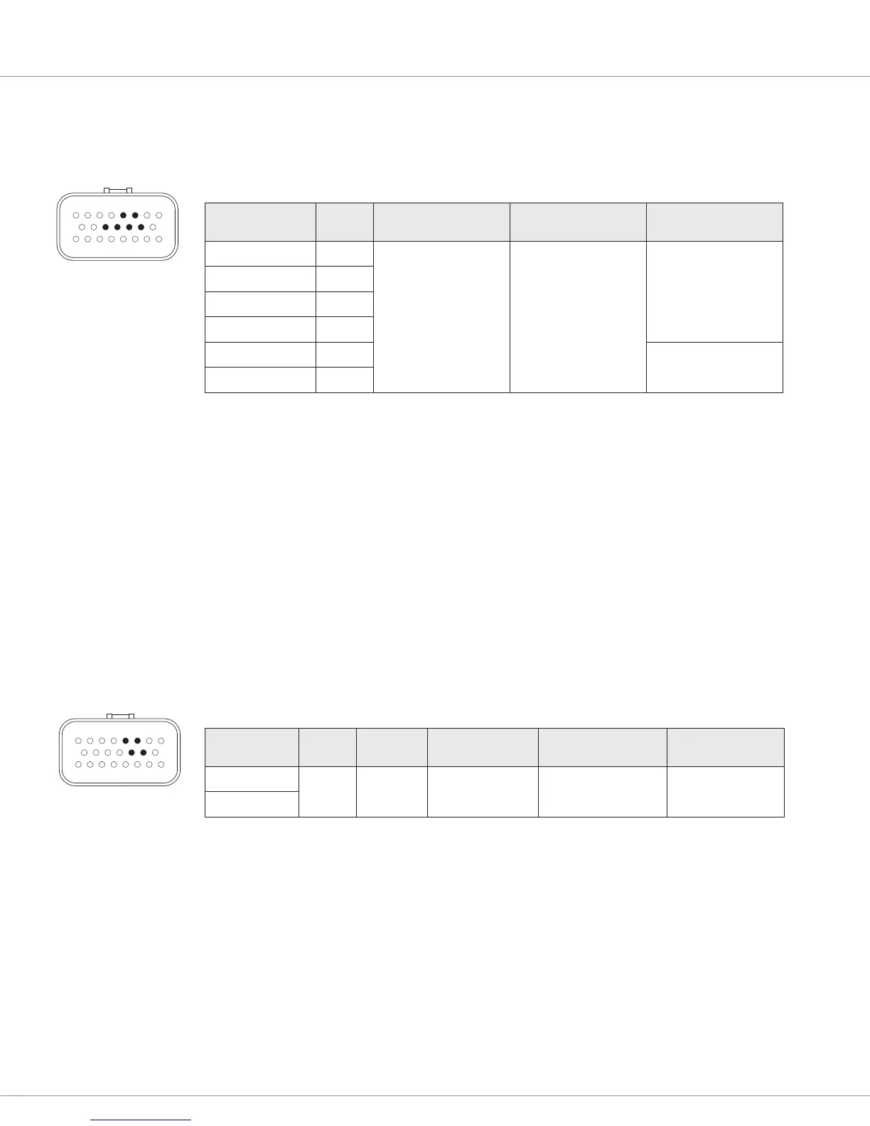
ANALOG INPUT SPECIFICATIONS
Signal Name Pin Voltage Input Impedance
Protected Voltage
Range
Analog Input 1 14
Nominal input voltage:
0–15V
Input Max. reverse
voltage: -1.7V
Voltage Input Type:
~21 KΩ
Resistance input type:
~1 KΩ
-1 V to B+
Analog Input 2 13
Analog Input 3 6
Analog Input 4 5
Analog Input 5* 11
-0.3 to 12 V
Analog Input 6* 12
* Can be used as serial port on 1353-4101 and -6101.
e maximum resistive input on each analog input is 7.5 kΩ. e resistive or voltage type of analog
input can be selected by a Curtis programmer (1313/1314) or CAN SDO message.
ese six analog inputs can also be used as digital inputs. A unique feature of these digital inputs is
that the active high/low thresholds are completely programmable. us, these inputs can be used
with analog sensors to detect conditions like over/under pressure, high/low level points, etc.
Encoder Inputs
Analog Inputs 1 – 4 can be congured as two encoder inputs (Encoder 1A&1B and Encoder 2A&2B).
ese standard quadrature encoder inputs accept open collector encoders with pull-up resistors. e
encoders can be powered from the +5V supply (Pin 3) or the +12V supply (Pin 10) while using the
I/O GND as a common.
ENCODER INPUTS SPECIFICATIONS
Encoder Phase Vth LO Vth HI Frequency Max Input Impedance
Protected
Voltage Range
A
1.0 V 2.2 V 15 kHz
1KΩ (internal pull-up
to +4.4 V)
-1 V to B+
B
81
2316
9 15
81
2316
9 15