2 — INSTALLATION AND WIRING
Curtis 1353 CANopen Expansion Module Manual – June 2017 Return to TOC
pg. 8
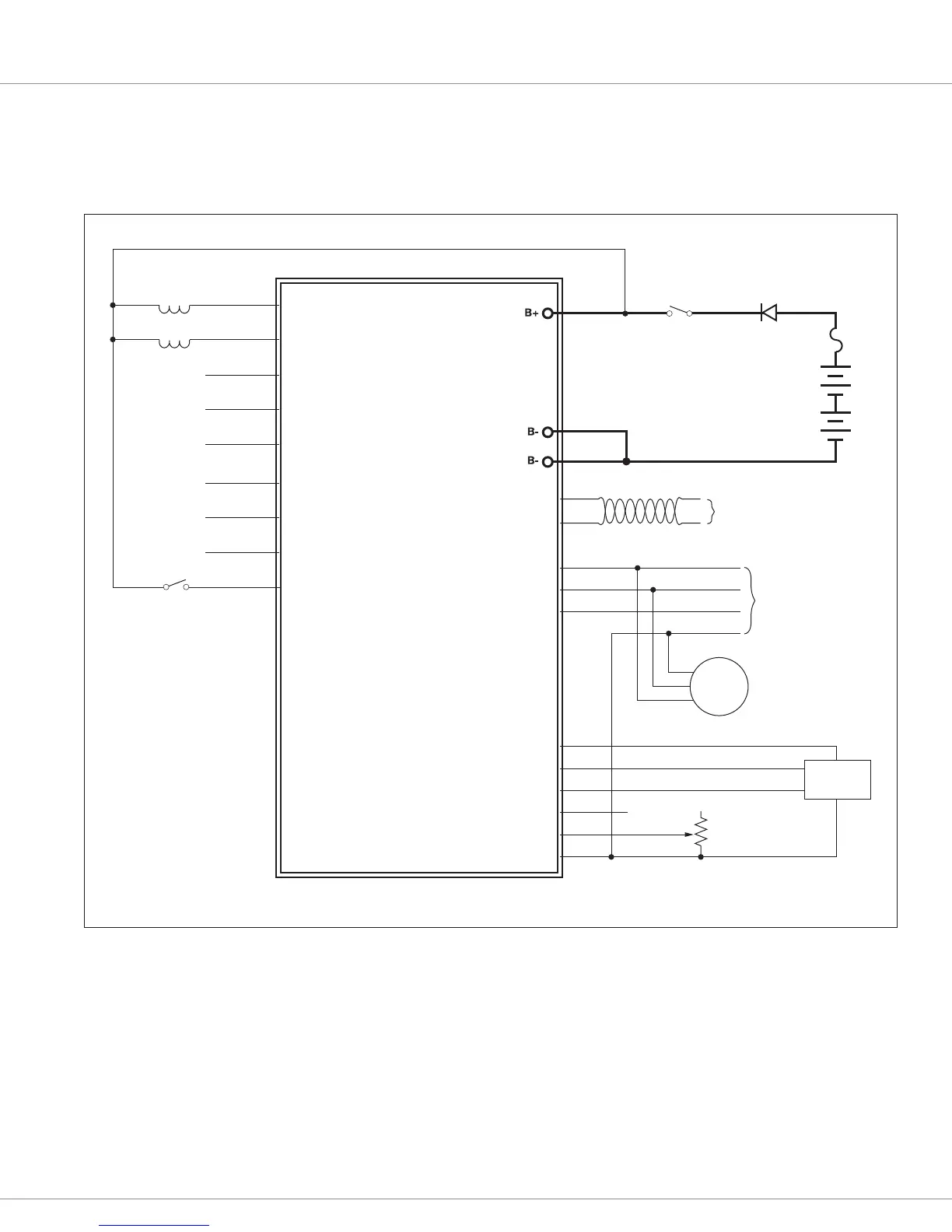
WIRING: BASIC CONFIGURATION
A basic wiring diagram is shown in Figure 3, and described below. e diagram shows the standard
power and battery connections, as well as some basic uses for the inputs and outputs.
J1-7
J1-8
J1-2
J1-9
J1-1
J1-23
J1-22
J1-21
J1-20
J1-19
J1-18
J1-17
J1-16
J1-15
J1-3
KEYSWITCH
SWITCH
BATTERY
(12–80V)
REVERSE
POLARITY
PROTECTION
PROPORTIONAL
VALVE
CONTACTOR
CAN PORT
1353
ANALOG INPUT 1/ENCODER 1A
ANALOG INPUT 2/ENCODER 1B
ANALOG INPUT 3/ENCODER 2A
ANALOG INPUT 4/ENCODER 2B
I/O GND
INPUT/OUTPUT 1
INPUT/OUTPUT 2
INPUT/OUTPUT 3
INPUT/OUTPUT 4
INPUT/OUTPUT 5
INPUT/OUTPUT 6
INPUT/OUTPUT 7
INPUT/OUTPUT 8
INPUT/OUTPUT 9
CAN H
CAN L
+5V
ENCODER
J1-14
J1-13
J1-6
J1-5
J1-4
0–15V IN
RESISTIVE THROTTLE,
RTD, etc.
J1-10
J1-11
J1-12
SERIAL PORT
(4-pin Molex)
4
3
1
2
DISPLAY
8
6
5
+12V
ANALOG INPUT 6/RX
ANALOG INPUT 5/TX
Figure 3
Basic wiring diagram, Curtis 1353 CANopen expansion module.
Power Connection
e battery is connected to the module’s B+ pin though a fuse, a diode, and a keyswitch. e fuse
protects the wiring in the event of a short or failure. e return path of the coils is also brought back
to the B+ pin to utilize the yback diodes connected inside the 1353 between B+ and each driver
output.
e keyswitch is used to turn on the system. When the keyswitch is closed, B+ goes high and the
1353’s power supply brings up the module.