2 — INSTALLATION AND WIRING
Curtis 1353 CANopen Expansion Module Manual – June 2017 Return to TOC
pg. 14
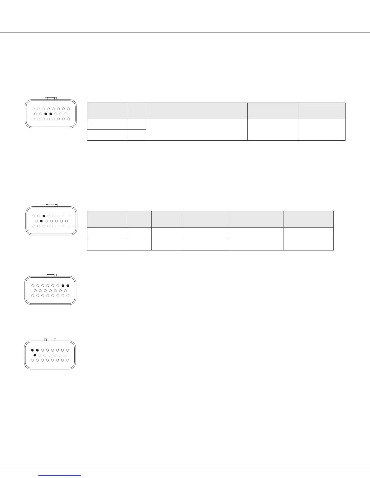
Serial Port (Models 1353-4101 and 1353-6101 only)
On selected models, Pins 11 & 12 can be congured as a serial port or as analog inputs via SDO. e
Curtis programmer can connect to this serial port using pins 11 & 12 along with I/O GND (Pin 4)
and +12V supply (Pin 10); see wiring diagram, Figure3. e Curtis Model 840 also can be connected
to this port.
SERIAL PORT SPECIFICATIONS
Signal Name Pin Supported Protocol/Devices Data Rate
Protected
Voltage Range
TX 11
1313 Handheld Programmer, 1314 PC
Programming Station. Curtis 840 Display
As required, 9.6
to 56kbps
-0.3 V to 12 V
RX 12
Auxiliary Power Supplies
e 1353 provides +12V and +5V auxiliary output power for low power circuits such as a ngertip
joystick, electronic throttle, Curtis programmer, or remote I/O boards. e return line for these low
power circuits is I/O GND (Pin 4). e maximum total combined output current is 200 mA.
AUXILIARY POWER SUPPLY SPECIFICATIONS
Signal Name Pin V out V out Tolerance I out (Max) Ripple/Noise
-12 V 10 12 V 10 %
–100 mA
2%
-5 V 3 5 V 5 %
–100 mA
2%
CANbus Interface
e CANbus interface will comply with CAN2.0B, active from 50 kbit/s to 1Mbsp communication rate.
The 1353 will be terminated by an internal 1 kΩ resistor across the CAN High and Low
communication pins. is assumes a mid-truck connection (not end-of-line). If the 1353 is placed at
the end of the communication lines, an external 120 Ω, ½ W resistor must be added across the lines.
Power
e power pins are each capable of carrying up to 9 A. Every application must use B+ (Pin 1) and
one or both of the B- connections (Pins 2, 9).
Since the 1353’s nine drivers can sink a maximum combined load of 18 A, you will need to determine
the application’s maximum total loading on B-. To prevent the pin from overheating, the proper
wire gauge must be used and, if the load is greater than 9 A, both B- pins connections are required.
If it is determined that both B- pins are required, you must also determine the load on B+. is
requires either knowledge of the expected PWM or actual in-application measurements. The
combined average current recirculating through the B+ pin cannot exceed 9 A. is can be an issue
if the inductive loads are specied at a lower voltage than the battery supply as the applied PWM
would normally be reduced so as not to exceed the average applied voltage or current. e lower
PWM in turn raises the average current owing theourgh the B+ pin as the load current recirculates
for a greater portion of the PWM period.
81
2316
9 15
81
2316
9 15
81
2316
9 15
81
2316
9 15