"##
The Model 803 Installation Kit includes a
pre-assembled mating connector with
5” terminated wires.
Ask for Curtis Part Number 15369002.
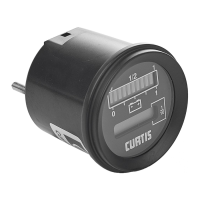
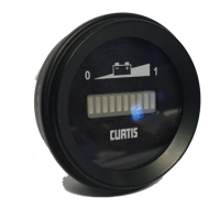
The Model 803 fits into a dash-panel cutout measuring
2
1
/
16
” (52 mm).
Terminal Assignment (see diagram on page 13)
.235&77*5<
Single voltage models: Pin 8 to battery +; Pin 7, open.
Dual voltage models: When vehicle voltage is the higher
voltage of the 2 operating voltages, Pin 8 connects to
battery +; Pin 7, open. When vehicle voltage is the lower
of the 2 operating voltages, Pin 7 connects to battery +,
Pin 8, open.
The discharge indicator uses Pin 7 or 8 for its battery
state-of-charge measurements. Connection are to be
made as close as possible to battery to prevent voltage
drops that will cause errors in discharge indicator
readings. The connection is not to be switched by
the vehicle’s keyswitch.
.2&77*5<>
Connect to battery ground as close to battery
as possible.
.2*<6:.7(-
The keyswitch turns on and off the LED display of the
battery discharge indicator. Monitoring of the battery
continues when Pin 2 is turned off and the display
is not lit.
The hour meter display is unaffected by Pin 2, although
it cannot accumulate more time as long as the
keyswitch pin is not energized. The control inputs HRM
(+) and HRM (–) are enabled by the keyswitch. Pin 2
is connected to the vehicle’s keyswitch.
.26385*7*5327530
In normal operation, Pin 1 or 6 is connected and the
other is left open. Only one of these pins is connected
when using normal hour meter function. It is possible to
OR the hour meter between the two inputs so that it
accumulates the total time either system is on. Hour
meter control logic is detailed in Table 2.