10
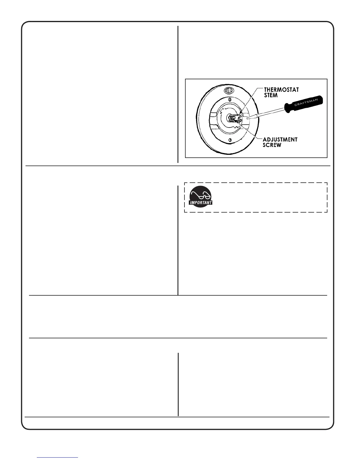
ELECTRIC THERMOSTAT ADJUST
On electric urns, thermostats are set at the fac-
tory to cut off at 200ºF. We do not recommend
changing this. If necessary, adjustment is as fol-
lows:
1. Rotate the thermostat knob to the right to the
BOIL position. Pull off the knob.
2. In the thermostat stem, locate the tiny adjust-
ment screw (see illustration). Using a small
screwdriver, adjust the temperature up or
down:
a. Turning the screw ¼ turn to the left will
increase the temperature about 20°F.
b. Turning the screw ¼ turn to the right will
decrease the temperature by 20°F.
c. To set the thermostat precisely at 200°F,
insert a thermometer probe into the water
The urn must be away from wall no less than 6”
and must have plenty of cross ventilation.
The water supply connection is the same in all
RU models. All that is needed is 1/4” copper tub-
ing with a 1/4” are nut and some sort of water
lter in the line before water enters the unit. Once
the water connection is complete, open the water
line, then plug in the power cord into an 115V out-
let. To facilitate the lling of the water jacket, you
can open the emergency rell faucet (red knob)
behind the unit, to increase the speed of lling the
urn. Water must be above the base of the center
gauge glass before turning on the heat.
IMPORTANT Be sure to shut off the
emergency rell valve after lling to
prevent overow!
GAS CONNECTION
All RU automatic urns are supplied with a
3/8” pressure connector at the end of the gas
valve. This valve is connected to the thermostat.
Use 3/8” O.D. stainless steel ex tubing to make
the connection from the urn to the gas valve in
your facility. When the connections are complete,
turn the gas on. Check the line for leaks.
MAIN BURNER ADJUSTMENT
To adjust the main burner ame, turn the thermostat dial to 6½ for 195ºF or 7 for 200ºF. For older units
(made before serial number 12327781), turn the screw under the gas cock handle in either direction to
regulate the ow of gas to the main burner.
PROCEDURE FOR LIGHTING OR RELIGHTING
1. TurnGASCOCKhandleto“off”position,andthermostatdialto
lowest temperature position.
2. Waitsufcientlengthoftimetoallowgaswhichmayhaveac-
cumulated in burner compartment to escape.
3. Turnpilotdialto“Pilot”position.
4. Pushinthepilotdial(thedialhasaslightinwardtravel)andro-
tate it to the PILOT position. On older units, there is a separate
red SET button that must be pushed in to allow the dial to turn.
5. Continuepressinginthedialwhilelightingthepilotburner.The
pilot is located inside the burner compartment, between the
main burners.
5. Oncelit,continuepressinginthedialfor30seconds.Ifthe
pilotamedoesnotremainlit,repeatoperationallowinglonger
period before releasing pilot dial.
6. TurnthepilotdialtotheONposition.Turnthethermostatdialto
the desired position. The main burner will then ignite.
jacket through the steam hole (just under
the spray head). Turn the screw ½ turn to
the left. When the thermometer reaches
200°F, slowly turn the adjustment screw to
the right until the pilot light turns off.
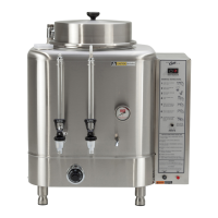
GAS URN INSTALLATION
 Loading...