20
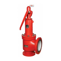
Figure 9.3
9. Thread the Disc Holder [6] onto the Stem Retainer [14] using a
special assembly block (see Figure 9.3). Do not attempt to hold the
Stem Retainer [14] on the guiding surface. Thread the Lock Screw
[19] counter clockwise until contact is made with the Disc Holder [6].
Tighten to lock the assembly together.
10. Thread the Disc [4] into the Disc Holder [6]. Be sure the Disc [4] is
free-floating. (Figure 9.4)
11. Place the Sleeve Guide [8] over the Stem Retainer [14] with the long
lift stop facing down. Be sure that the guiding motion is smooth.
12. Thread the Stem [9] and Stem Retainer [14] together. Be sure this
connection is free-floating. (Figure 9.5)
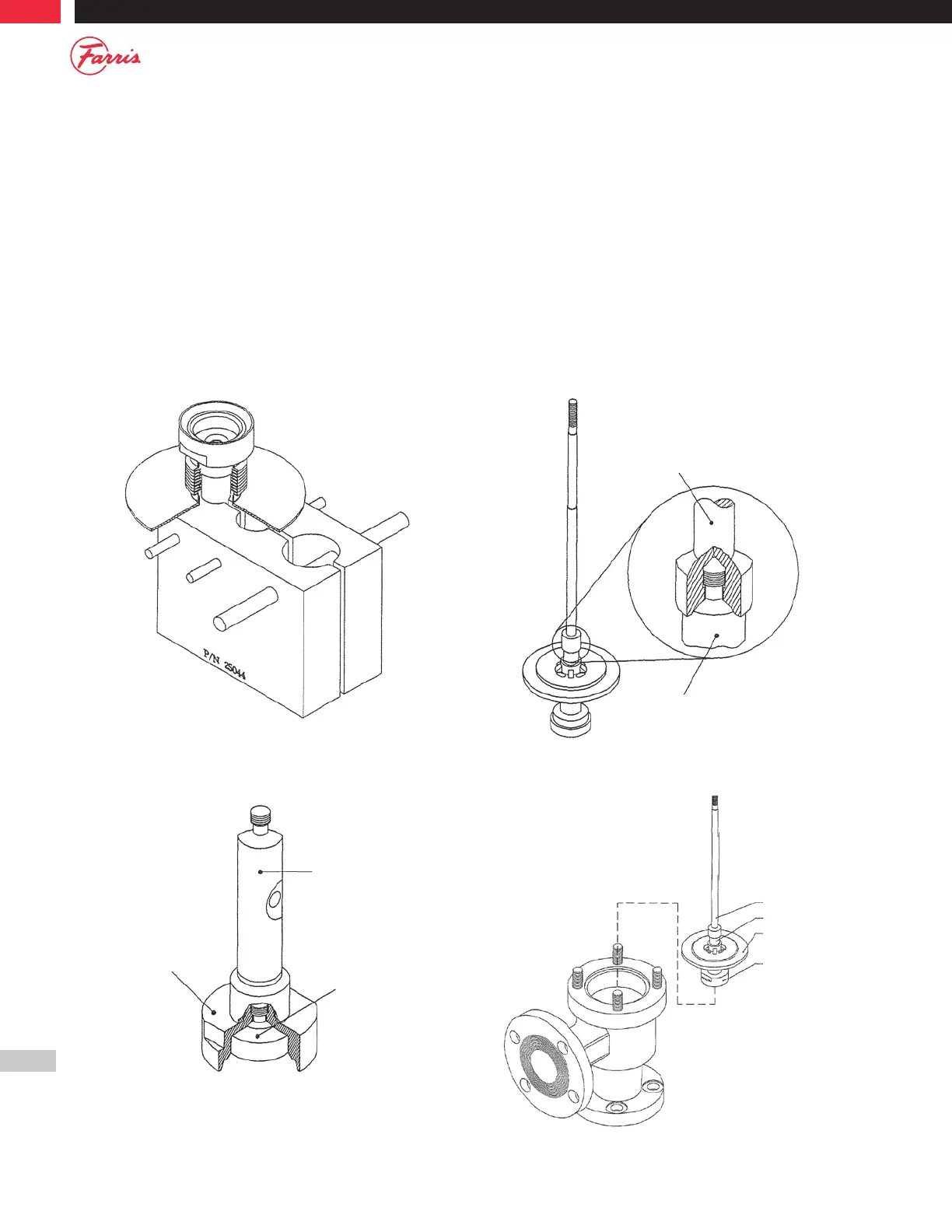
13. Lower the Assembly (Stem [9], Sleeve Guide [8], and Disc Holder
[6]) into the Body [1] counter-bore. (Figure 9.6)
14. Place the Bonnet Gasket [23] on the Sleeve Guide [8], or secure with
sealant in the Bonnet [2] counter-bore.
15. Place the lower Spring Button [17] on the Stem [9]. Caution – in
some valve sizes the upper and lower Spring Buttons [17] are
different.
16. Place the Spring [20] on the lower Spring Button [17].
Figure 9.6
Stem Retainer
Sleeve Guide
Stem
Disc Holder
Figure 9.4
Stem Retainer
Disc
Disc Holder
Figure 9.5
Stem
Stem Retainer