33
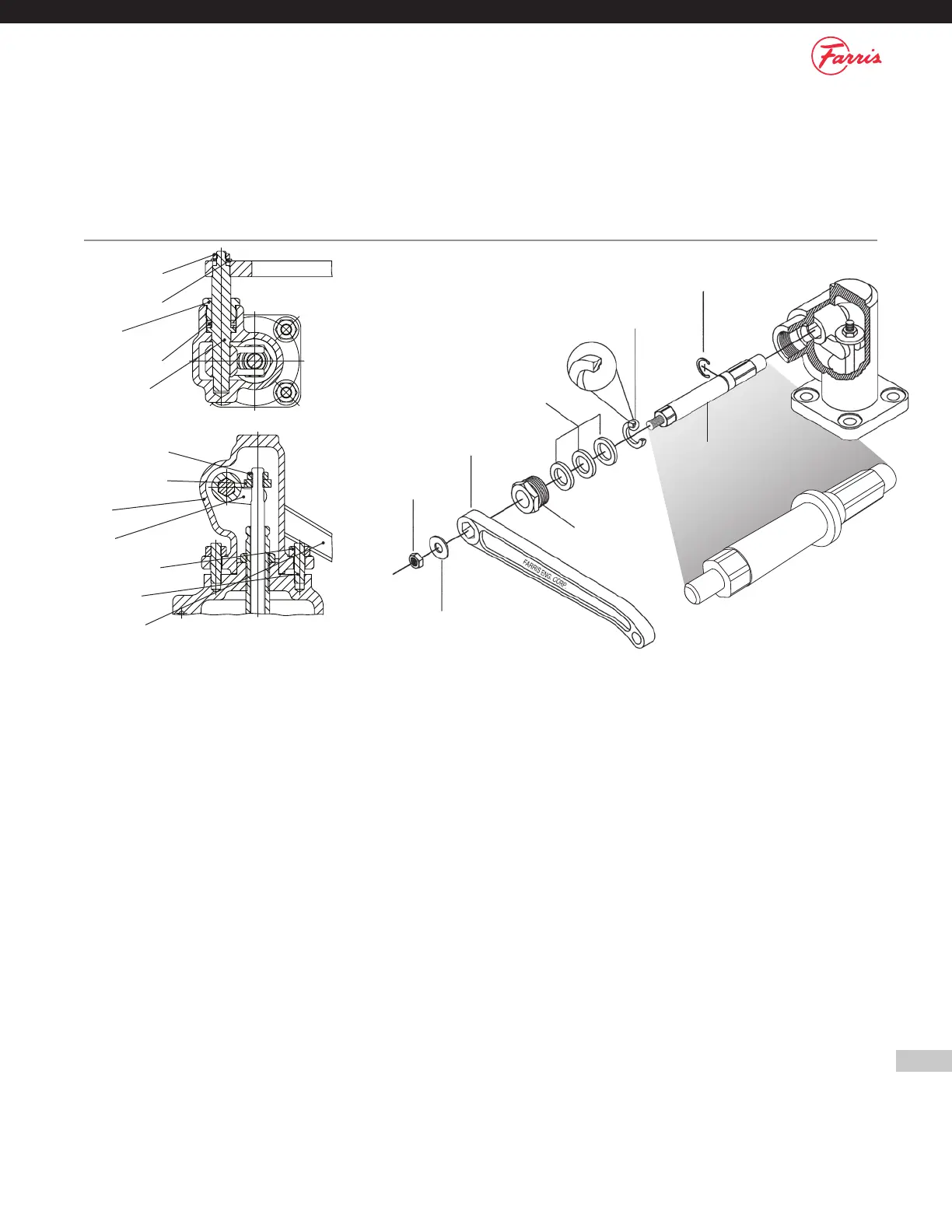
Hex Jam Nut
Test Lever
Gland
Packing Rings
Cam Shaft Ring
Retaining Ring
Cam Shaft
Plain Washer
Appendix D: Cap Construction
Figure D.1 – Packed Lever Cap Construction
2600 Series, All Sizes
Hex Jam Nut
Plain Washer
Gland
Packing Ring
Cam Shaft
Stem Jam Nut
Stem Test Nut
Cap
Cam
Cap Hex Nut
Cap Stud
Test Lever
Section VIII of the ASME Code requires the use of a lifting device on all steam, air and hot water (over 140°F/60°C) applications. Packed levers should be
used on all liquid applications or where cap tightness is a requirement. Levers should be inspected for proper operation and parts replaced as needed.
Packed Levers
1. Thread the Stem Test Nut onto the Stem.
2. Thread the Stem Jam Nut onto the Stem.
3. Place the Cap Gasket on the Bonnet.
4. Place the counter-bored side of the Retaining Ring onto the Cam Shaft.
5. Place the Packing Rings over the Cam Shaft and into the Retaining
Ring cavity.
6. While holding the Cam in-place inside the Cap, slide the Cam Shaft
through the hole in the side of the Cap and through the Cam.
7. Place the Cap onto the Bonnet ensuring that the cap protrusion is
facing the valve outlet.
Packed Lever Construction Assembly/Disassembly Instructions
The following instructions are assembly instructions. For disassembly, reverse the order. Parts identification may be found above. Assembly procedures
for the balance of valve is identical for all cap design options: plain cap, open lever, bolted cap and packed lever.
8. Thread the Cap Studs through the Cap into the Bonnet and tighten.
9. Adjust the Stem Test Nut until there is 1/8" clearance between Stem
Test Nut and the Cam.
10. Tighten the Stem Jam Nut.
11. Thread the Gland into the Cap.
12. Place the Test Lever on the Cam Shaft. Ensure that the Test Lever Is
oriented away from the valve outlet.
13. Place the Plain Washer over the Cam Shaft.
14. Thread the Lever Hex Jam Nut onto the Cam Shaft.