34
Open Lever Cap Construction Assembly/Disassembly Instructions
The following instructions are assembly instructions. For disassembly, reverse the order. Parts identification may be found above.
Assembly procedures for the balance of valve is identical for all cap design options: plain cap, open lever, bolted cap and packed lever.
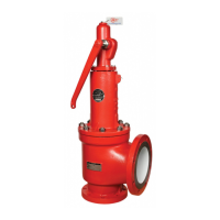
For single acting lever only:
1. Thread the Stem Test Nut onto the Stem.
2. Thread the Stem Jam Nut onto the Stem.
3. Place the Cap onto the Bonnet ensuring that the cap protrusion is
facing the outlet of the valve.
4. Thread the Cap Studs through the Cap into the Bonnet and tighten.
5. Place the Lever Round Head Rivet through the Test Lever and Cap
hole and secure with the Cotter Pin.
6. Adjust the Stem Test Nut so there is 1/8" clearance between
the Test Lever fulcrum and the Stem Test Nut.
7. Tighten the Stem Jam Nut.
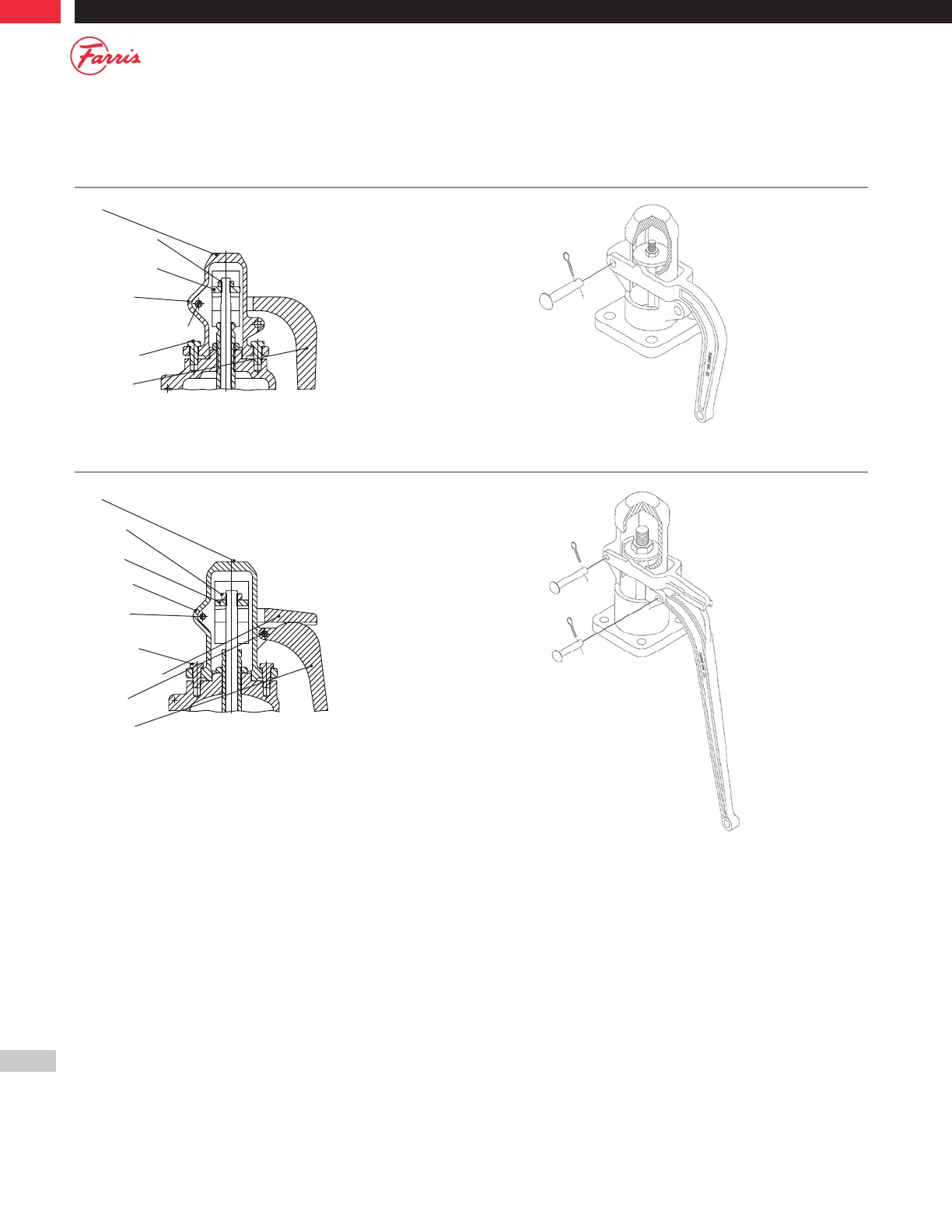
For double acting lever only:
1. Thread the Stem Test Nut onto the Stem.
2. Thread the Stem Jam Nut onto the Stem.
3. Place the Cap onto the Bonnet ensuring that the cap protrusion
is facing the outlet of the valve.
4. Thread the Cap Studs through the Cap into the Bonnet and tighten.
5. Place the Fork Round Head Rivet through the Test Lever Fork and
Cap hole and secure with a Cotter Pin.
6. Place the Lever Round Head Rivet through the Test Lever and Cap
hole and secure with the Cotter Pin.
7. Adjust the Stem Test Nut so there is 1/8" clearance between the Test
Lever Fork and the Stem Test Nut.
8. Tighten the Stem Jam Nut.
Figure D.2 – Open Lever (Single Acting)
2600 Series, Types 26( )A10, A11, A20, A21, All Sizes Except 8x10
Figure D.3 – Open Lever (Double Acting)
2600 Series, Sizes 1x2 Thru 6x10 Except
Types 26( )A10, A11, A20, A21, Sizes 8x10, All Types
Cap
Stem Jam Nut
Stem Test Nut
Cotter Pin
Lever RD. HD. Rivet
Cap Screw
Test Lever
Cap
Stem
Jam Nut
Test Lever
Test Lever Fork
Cap Screw
Cotter Pin
Stem
Test Nut
Fork RD.
HD. Rivet
Lever RD.
HD. Rivet
Open Levers