36
Appendix E: Critical Dimensions
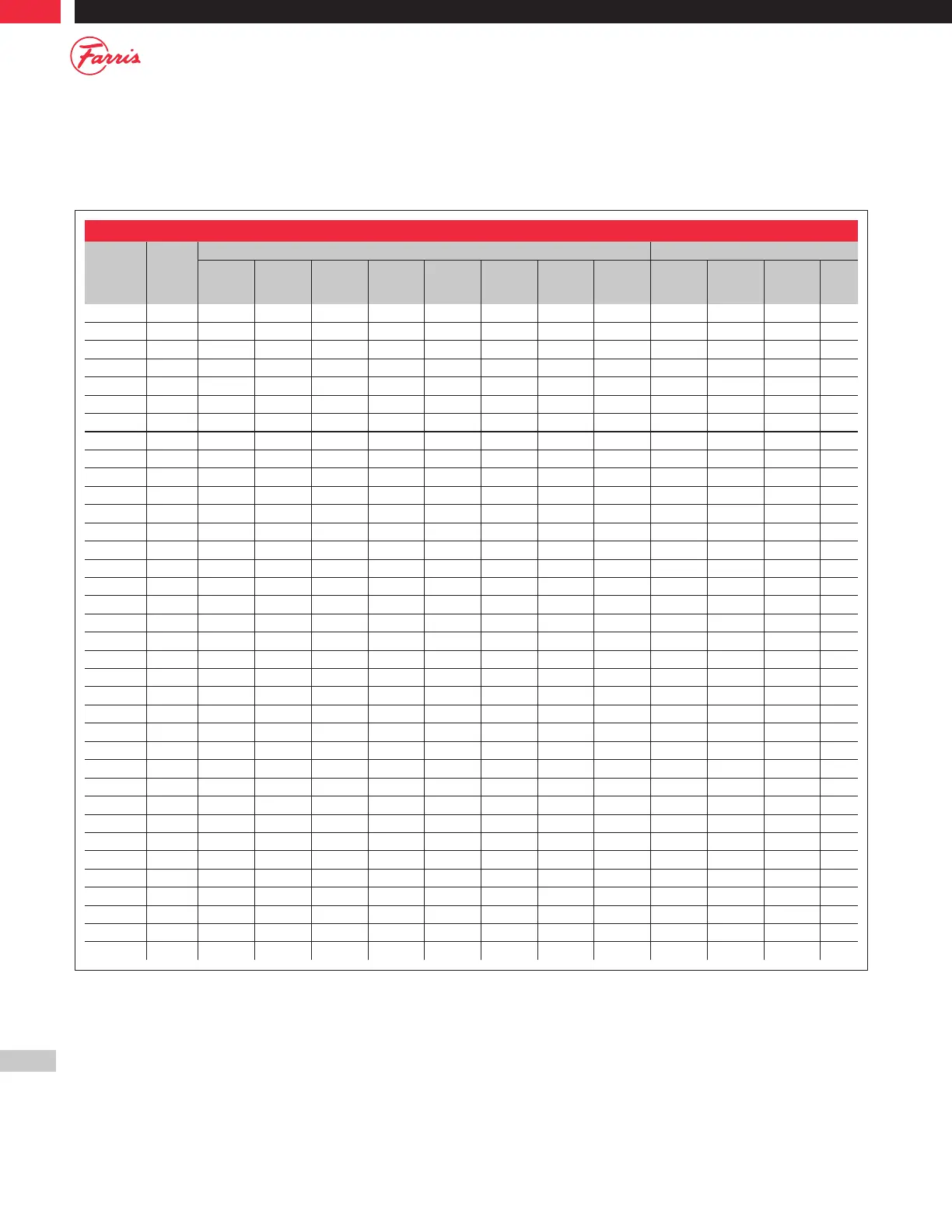
These dimensions apply to 2600 Series valves with “A10” through “A15” serial numbers and supersede any dimensions
provided in previous revisions to the manual.
General Notes:
1. Z column designates flange class number to be inserted in type number, example: 26D( )( )3 would designate any of the D orifice 2600 designs
(conventional or bellows) with a 600# inlet flange.
2. For type 2600 (A10 & A11 Serials) see Figure 2. For type 2600L (A14 & A15 serials) see Figure 3.
3. Does not apply to valve type numbers designated for use at a temperature range of 801 to 1000 F.
4. For serial numbers suffixes; A10/G, A11/G, A14/G, A15/G, please consult factory for critical dimensions.
Table E.1: Metal Seats - Serial Number Suffixes: A10 & A11 / A14 & A15
Type Z
1
Nozzle Dimensions Disc Dimensions
A
+.010
-.000
B
+.000
-.005
C
+.005
-.000
D
min
E
min
F
min
L
min
Nozzle
Fig.
H
+.000
-.005
J
+.005
-.000
N
min.
Disc
Fig.
26D( )( )z 0 - 3 0.437 0.520 0.580 0.010 0.005 0.010 4.125 2, 3
2
0.480 – 0.156 1
4 - 6 0.437 0.520 0.614 0.005 – 0.010 4.375 1
26E( )( )z 0 - 3 0.535 0.585 0.645 0.010 0.005 0.010 4.062 2 0.545 0.725 0.234 2
4 - 6 0.535 0.585 0.685 0.005 0.005 0.010 4.375 2
26F( )( )z
4
0 - 1 0.687 0.720 0.780 0.005 0.005 0.010 4.250 2
2 - 5 0.687 0.720 0.780 0.005 0.005 0.010 4.375 2 0.680 – 0.265 1
6 0.687 0.720 0.820 0.005 0.005 0.010 4.375 2
26G( )( )z 0 - 1 0.844 0.885 0.945 0.010 – 0.010 4.093 1
2 - 4 0.844 0.885 0.945 0.005 – 0.010 4.234 1 0.845 – 0.296 1
5 0.844 0.885 0.995 0.005 – 0.010 5.031 1
6 0.844 0.885 0.995 0.005 0.010 0.010 5.031 2
26H( )( )z 0 - 1 1.054 1.110 1.170 0.005 – 0.010 4.937 1
2 1.054 1.110 1.170 0.010 – 0.010 4.156 1
3
3
1.054 1.110 1.210 0.005 – 0.010 5.031 1 1.070 – 0.296 1
4 - 5 1.054 1.110 1.210 0.005 – 0.010 5.031 1
26H( )( )33 1.054 1.110 1.170 0.010 – 0.010 4.156 1
26J( )( )z 0 - 1 1.350 1.416 1.476 0.005 – 0.010 4.125 1
2 - 3 1.350 1.416 1.496 0.005 – 0.010 5.187 1
4
3
1.350 1.416 1.516 0.010 – 0.010 6.562 1 1.376 – 0.296 1
5 1.350 1.416 1.516 0.010 – 0.010 6.562 1
26J( )( )34 1.350 1.416 1.496 0.005 – 0.010 5.187 1
26K( )( )z 0 - 3 1.612 1.730 1.830 0.010 0.010 0.010 6.546 2
4
3
1.612 1.730 1.830 0.005 0.010 0.010 7.921 2 1.570 – 0.296 1
5 1.612 1.730 1.830 0.005 0.010 0.010 7.921 2
26K( )( )34 1.612 1.730 1.830 0.010 0.010 0.010 6.546 2
26L( )( )z 0 - 1 2.009 2.106 2.166 0.005 0.010 0.010 6.484 2 2.056 – 0.312 1
2 - 5 2.009 2.106 2.196 0.010 0.020 0.010 7.609 2
26M( )( )z 0 - 4 2.257 2.366 2.446 0.005 0.030 0.010 7.546 2 2.306 – 0.375 1
26N( )( )z 0 - 4 2.478 2.598 2.678 0.010 0.030 0.010 7.546 2 2.538 – 0.375 1
26P( )( )z 0 - 4 3.004 3.080 3.200 0.010 0.030 0.010 7.500 2 3.020 – 0.421 1
26Q( )( )z 0 - 3 3.952 4.080 4.220 0.010 0.030 0.010 8.750 2 4.020 – 0.453 1
H26Q( )( )3 3.952 4.080 4.220 0.010 0.030
0.010 8.750 2
26R( )( )z 0 - 3 4.758 4.985 5.145 0.005 0.030 0.010 8.031 2 4.895 – 0.703 1
H26R( )( )3 4.758 4.985 5.145 0.005 0.030 0.020 8.031 2
26T( )( )z 0 - 2 6.070 6.366 6.546 0.005 0.030 0.010 10.406 2 6.256 – 0.953 1
H26T( )( )3 6.070 6.366 6.546 0.005 0.030 0.010 10.406 2