19
9. Assembly Instructions
Lubrication and Sealant:
Threaded parts should be lubricated to prevent galling, especially parts
made of similar materials. In addition, guides and pivot points should
contain lubricant which is compatible with the service conditions. Sealant
should also be applied to prevent fluid from escaping valve boundaries,
especially if back pressure is present. The adjacent table lists the
suggested lubricant and sealant for air, steam, and liquid service.
Service conditions may dictate that other lubricant or sealant be used.
Code for Above Recommended Lubrication and Sealant
A = Bostic Never Seez
B = Molykote 3452
D = No Lubrication
* Service conditions may require an alternate lubricant or sealant
Item Thread Lubrication Air Steam Liquid
1 Pipe Plug/Body A A A
2 Lock Screw (BDR) Body A A A
3 Blowdown Ring/Nozzle D D D
4 Lock Screw Stud/Jam Nut (BDRLS) A A A
5 Disc/Disc Holder A A A
6 Stem Retainer/Disc Holder (if Applicable) A A A
7 Lock Screw (DH)/Stem Retainer A A A
8 Stem Retainer/Stem A A A
9 Pipe Plug/Bonnet (if applicable) A A A
10 Spring Adjusting Screw/Bonnet/Jam Nut A A A
11 Plain Cap/Bonnet (if applicable) A A A
12 Body Stud/Body/Hex Nut A A A
Guiding and Pivot Lubrication
13 Disc/Disc Holder A A A
14 Sleeve Guide/Stem Retainer D D D
15 Stem Retainer/Stem A A A
16 Spring Button/Stem A A A
17 Spring Button/Spring Adjusting Screw A A A
Sealant
18 Body/Nozzle A A A
19 Body/Bonnet/Sleeve Guide/Gaskets A A A
20 Bonnet/Gasket/Cap (if applicable) A A A
21 Bellows Gasket B B B
Assembly Instructions
Farris 2600 Series valves should be assembled as described below.
Parts identification may be found in Figure 4.1 on page 8.
For torque requirements, please refer to Appendix H.
1. Thread the Nozzle [5] into the Body [1].
2. Thread the Pipe Plug [28] into the Body [1].
3. Thread the Blow Down Ring [7] onto the Nozzle [5].
4. Thread the Hex Nut [25] onto the Lock Screw Stud [13]. Thread the
Lock Screw Stud [13] into the Lock Screw (BDR) [12].
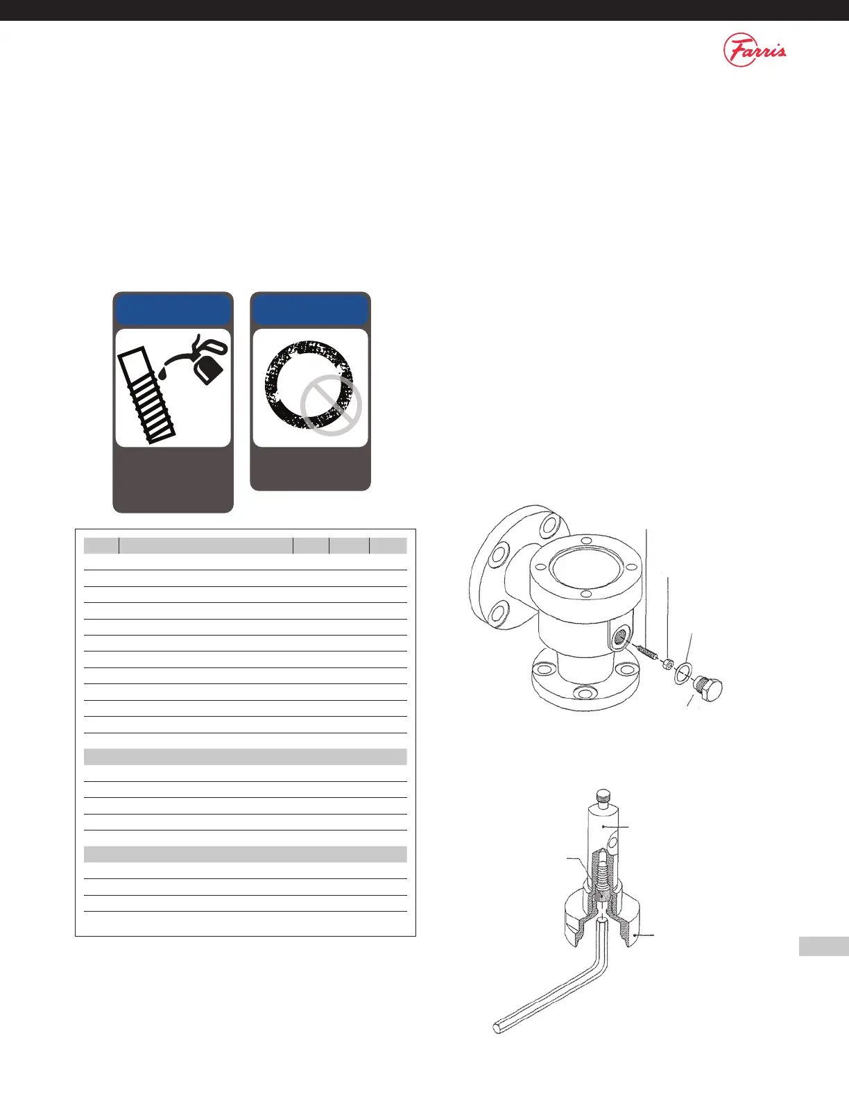
5. Thread the Lock Screw Assembly into the Body [1] including the
Lock Screw Gasket [24]. Adjust the position of the Lock Screw Stud
[13] so that it prevents rotation of the Blow Down Ring [7] yet does
not bind it. Use the position noted during disassembly. (Figure 9.1)
6. Thread the Body Studs into the Body [1].
7. Place the Body Gasket [22] in the Body [1] counter-bore.
8. Thread the Lock Screw [19] into the Stem Retainer [14]. (Figure 9.2)
Figure 9.2
Stem Retainer
Disc Holder
Lock Screw
Figure 9.1
Lock Screw Stud
Hex Nut
(B.D.R.L.S.)
Lock Screw
Gasket
Lock Screw
(B.D.R.)
NOTICE
Only a light film lubricant
should be applied to the
guiding surfaces. Too much
lubricant will hinder valve
performance.
NOTICE
Always use new gaskets
and packing when
reassembling valves.