29
Appendix B: Bellows Construction
Bellows require very thin materials to provide
the required flexibility. This results in a delicate
assembly which should be carefully handled. Do
not attempt to repair a bellows assembly. Any
pitting or surface corrosion are sure signs of
limited service life even though the bellows may
be pressure tight. All bellows assemblies should
be pressure tested in accordance with Figure
B.1. Any leakage should be cause for bellows
replacement. For BalanSeal bellows equipped
valves use the assembly fixture shown in Figure
B.2. Exercise care in handling the internal
assembly when equipped with a bellows as any
damage to the bellows in the form of a nick or dent will render the bellows
unfit for service. Bellows are not repairable.
1. Place bellows/stem retainer/disc holder assembly into bellows leak
test fixture with the bellows flange at the base.
2. Seal the flange of the bellows to the base of the bellows test fixture as
illustrated in Figure B.1.
3. Compress the bellows approximately 1/8 inch with a securing bar so
that the bellows does not elongate when pressure is applied as in
Figure B.1.
4. Fill the disc holder with water. Omit this step for D & E Balanseal
designs as these designs have a one piece disc holder/stem retainer.
5. Apply 30 psig pressure to the back side of the bellows.
6. Apply soapy water to bellows exterior to check
for bellows integrity.
7. If bubbles appear on bellows exterior there are pin holes
or a tear. Replace bellows and repeat the procedure.
8. Check to be sure the bellows/disc holder connection is leak tight. If
water in disc holder bubbles or the connection bubbles, tighten the
connection or replace gasket.
9. Vent pressure.
10. Release bellows assembly.
11. Air dry bellows assembly to remove soapy water.
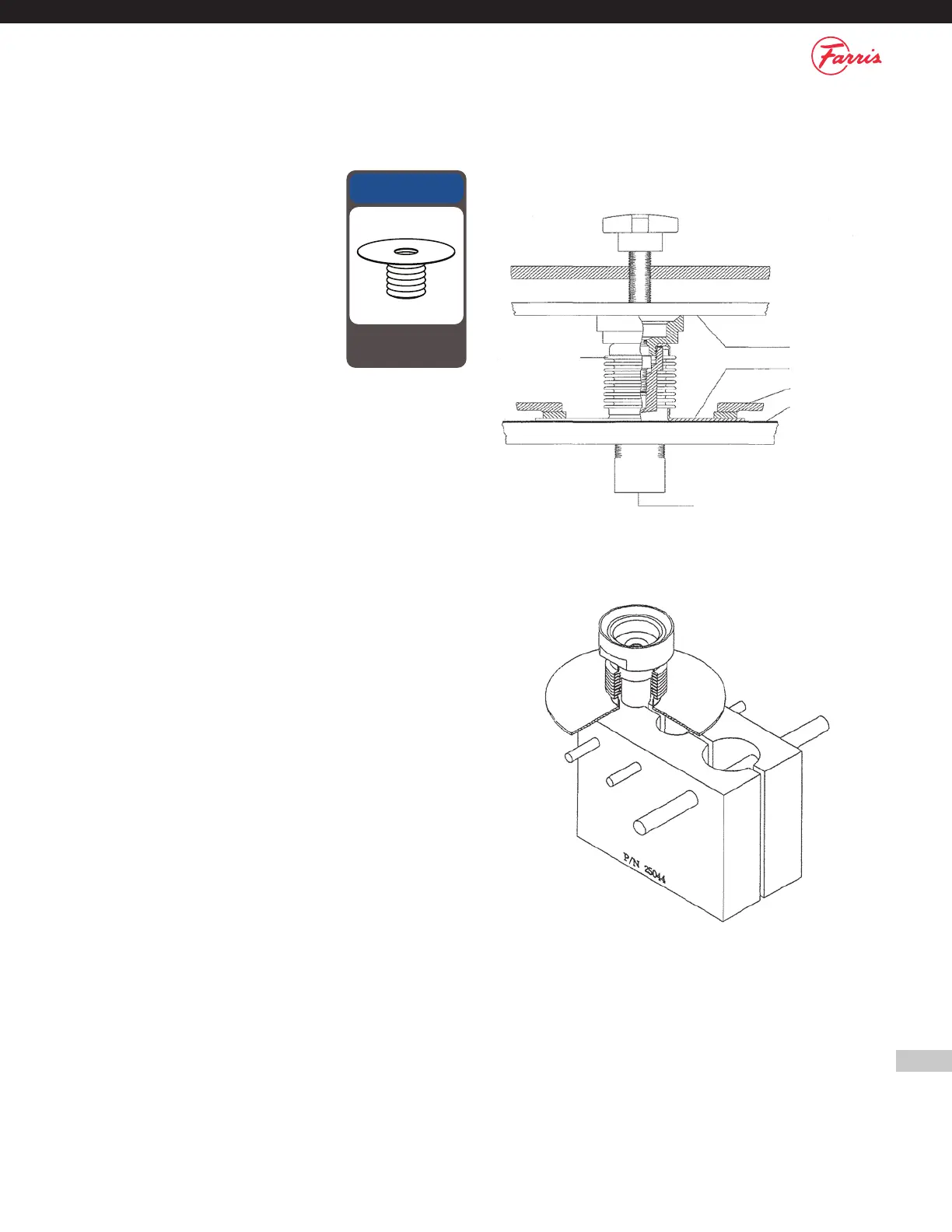
Figure B.1 Bellows Assembly Leak Test
Restraining Bar
Bellows Flange
Flange Clamp
Rubber Gasket
Inlet Pressure Source
Bellows
Assembly
Figure B.2
NOTICE
Bellows are not repairable
and should be replaced
if damaged.