30
BalanSeal
®
Bellows Construction
Assembly/Disassembly Instructions
The following instructions are assembly instructions. For disassembly,
reverse the order. Parts identification may be found below. Follow the
same procedures as for conventional type valves except as follows:
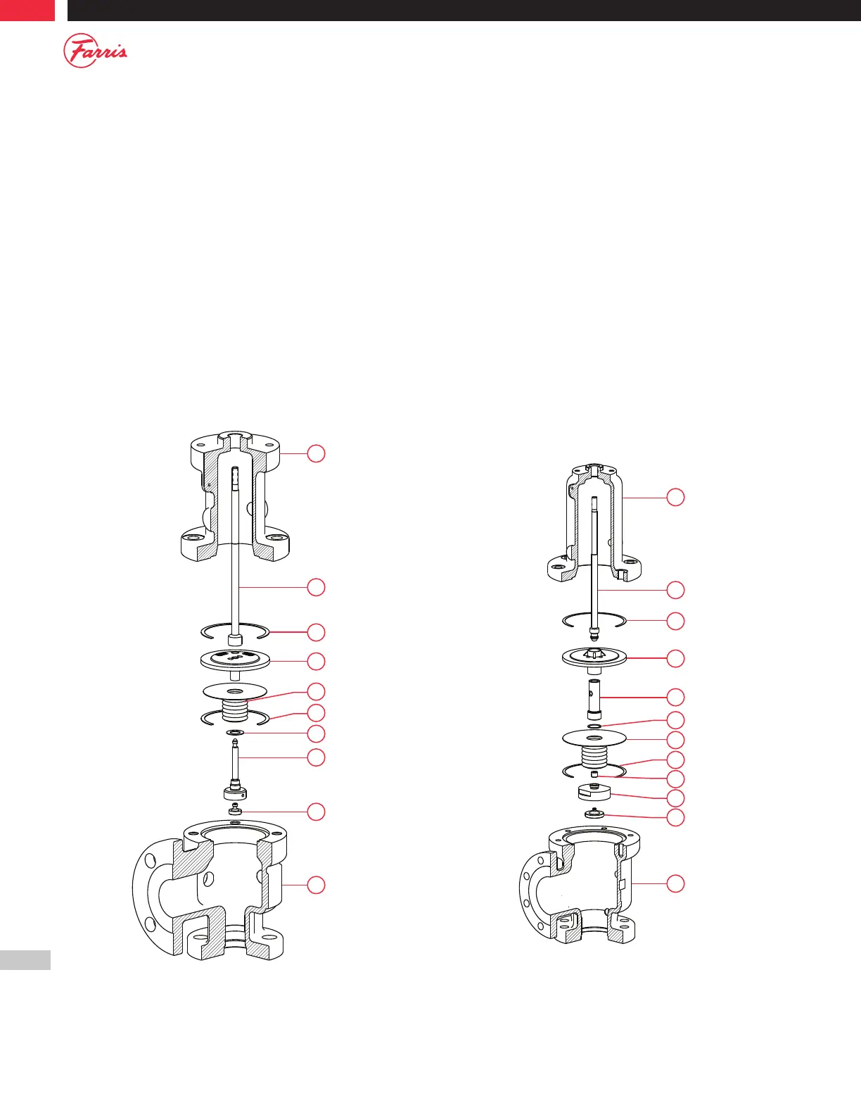
For D and E orifice valves only (Refer to B.3 below):
1. Place the Bellows Gasket [16] on Disc Holder [6].
2. Thread the Bellows [15] onto the Disc Holder [6] and securely tighten.
3. Do not thread Pipe Plug (Bonnet) into Bonnet [2]. Bonnet [2] must be
vented In accordance with ASME Code.
For all other orifices (Refer to B.4 below):
1. Place the Bellows Gasket [16] on the Stem Retainer [14].
2. Place the Bellows [15] on the Stem Retainer [14].
3. Thread the Disc Holder [6] to the Stem Retainer [14] using the special
assembly block.
4. Thread the Lock Screw [19] counter clockwise until contact is made
with the Disc Holder [6]. See Figure B.1 for bellows leak test.
5. Do not thread Pipe Plug (Bonnet) into Bonnet [2]. Bonnet [2] must be
vented In accordance with ASME Code.
Note: For F - K orifices, O-ring seat construction only, an additional Disc
Holder Lock Screw Gasket must be placed between the Stem
Retainer [14] and the Disc Holder [6].
2
2
1
1
4
4
8
8
6
6
16
16
15
19
15
14
22
22
9
9
23
23
Figure B.3 Figure B.4