32
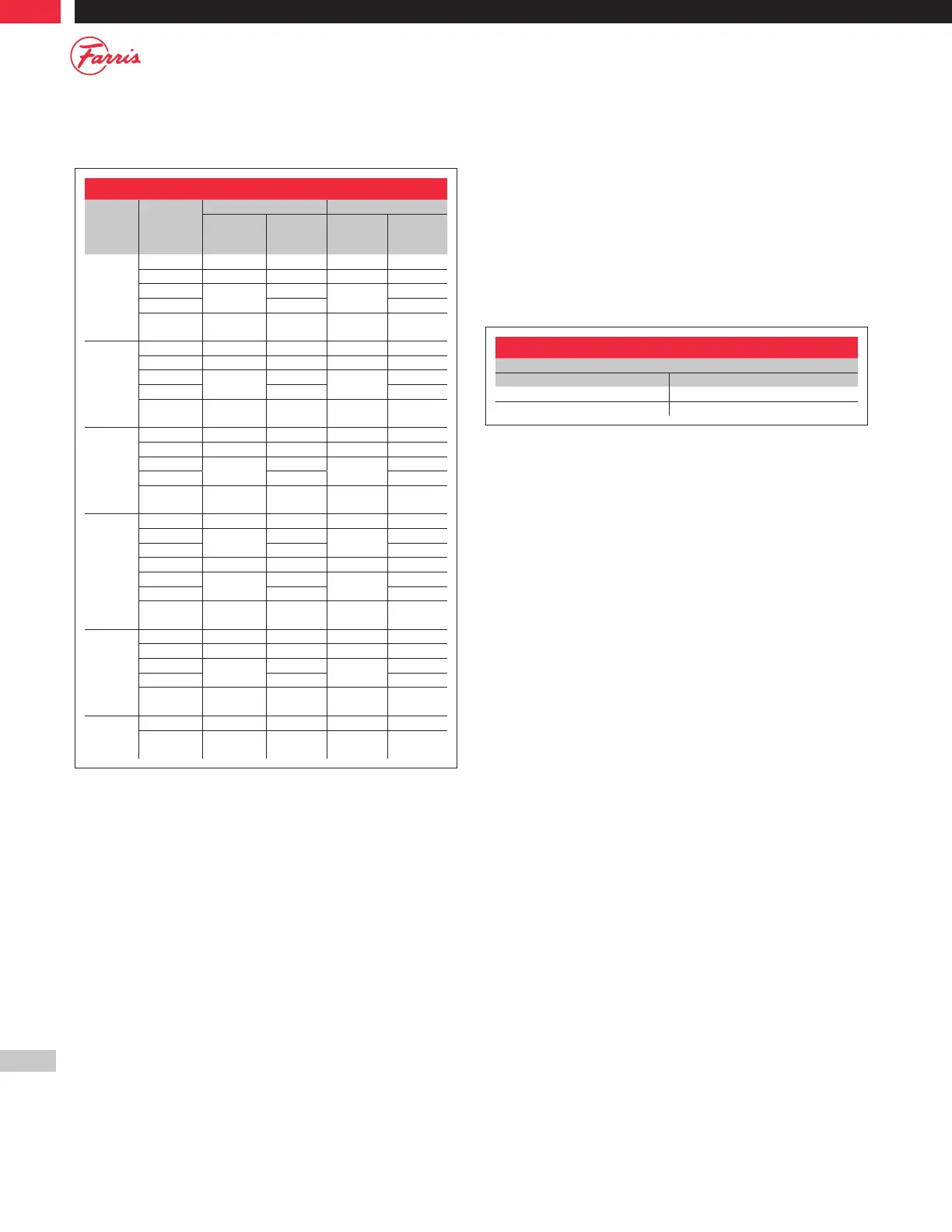
O-Ring Material Selection Table
Material
Temperature
Range °F
D to K Orifice L to T Orifice
Set
Pressure
(psig)
Durometer
(Shore A)
Set
Pressure
(psig)
Durometer
(Shore A)
Viton
4
-20 to 450 15 to 100 50 15 to 150 50
-20 to 450 101 to 650 75 150 to 450 75
-20 to 125
650 to 950
75
450 to 750
75
125 to 450 90 90
-20 to 450 950 to 1500 90
750 to
1500
90
Ethylene
Propylene
0 to 350 15 to 100 50 15 to 150 50
0 to 350 101 to 650 70 150 to 450 70
0 to 125
650 to 950
70
450 to 750
70
125 to 350 80 80
0 to 350 950 to 1500 80
750 to
1500
80
Buna N
0 to 200 15 to 100 50 15 to 100 50
0 to 200 101 to 650 70 100 to 450 70
0 to 125
650 to 950
70
150 to 750
70
125 to 200 90 90
0 to 200 950 to 1500 90
750 to
1500
90
Silicone
-150 to 450 15 to 100 50 15 to 100 50
-150 to 0
101 to 600
50
100 to 200
50
0 to 450 70 70
-150 to 450 600 to 850 70 200 to 450 70
-150 to 125
850 to 1100
70
450 to 750
70
125 to 450 80 80
-150 to 450
1100 to
1500
80
750 to
1500
80
Kalrez
-20 to 550 15 to 200 65 15 to 150 65
-20 to 550 201 to 650 80 150 to 450 80
-20 to 200
650 to 950
80
450 to 750
80
200 to 550 90 90
-20 to 550 950 to 1500 90
750 to
1500
90
Neoprene
-45 to 300 50 to 750 70 50 to 750 70
-45 to 300 751 to 1500 80
751 to
1500
80
Allen Key Sizes
Disc Holder Lock Screw
Orifices Allen Key Size
D thru K 1/8"
L thru U See Table 6.1
O-Ring Seat Construction
Assembly/Disassembly Instructions
The following instructions are assembly instructions. For disassembly,
reverse the order. Parts identification can be found on page 31. Follow the
same procedures as for conventional type valves except as follows:
To connect the Disc Holder to the Stem Retainer for O-ring valves, use
the allen key sizes found in Table C.1
For D and E orifice (Bellows Construction only)(See Figure C.1):
1. Place the O-ring in the Disc Holder groove.
2. Thread the Disc into the Disc Holder/Stem Retainer.
For orifices D and E (Conventional) through K only (See Figure C.1):
1. Place the O-ring in the Disc Holder groove.
2. Place the Disc into the Disc Holder.
3. Thread the Flat Head Machine Screw through the Disc into
the Disc Holder.
For orifices L through U only (See Figure C.2)
1. Place Disc in a vice with soft jaws or in a 3-jaw chuck. Be careful not to
hold too tight as the Disc can be damaged.
2. Place the O-ring into the Disc groove.
3. Place the O-ring Retainer on the Disc.
4. Thread the Flat Head Machine Screws through the O-ring
Retainer into the Disc.
5. Thread the Jack Screw Plug into the O-ring Retainer.
6. Thread the Disc into the Disc Holder (ensure the Disc is free floating).
General Notes:
1. Viton and Kalrez are registered trademarks of DuPont Performance Elastomers.
We reserve the right to substitute comparable fluorocarbon materials.
2. PTFE seat seals available on an application basis. Consult the factory
Table C.1