24
Air at ambient temperature shall be used as the pressure medium. The
valve shall be observed for leakage for at least 1 minute. The leakage rate
in bubbles per minutes shall not exceed the numbers listed in Table 10.1.
For an 0-ring seated valve, there shall be no leakage for 1 minute
(Zero bubbles per minute @ 95% of set pressure). (Figure 10.1)
Steam Testing
Steam service pressure relief valves which are set and adjusted on steam
shall be leak-tested on steam visualIy using a black background. There
shall be no visible leakage from the valve outlet when the inlet pressure is
held at 90% of the set pressure after popping and reseating. For set
pressure below 50 psig this test shall be conducted at 5 psig below set
pressure. The valve shall be observed for leakage for at least 1 minute.
This criteria applies to both metal and o-ring seated valves.
Liquid Testing
Liquid service pressure relief valves are set and adjusted on water shall be
leak-tested on water at near ambient conditions. Before starting the seat
tightness test, the set pressure shall be verified, and the outlet body bowl
shall be filled with water, which shall be allowed to stabilize with no visible
flow from the valve outlet. The inlet pressure shall be increased to the test
pressure. The valve shall be observed for 1 minute at the test pressure. For
valves set at 50 psig or below, the pressure shall be held at 5 psig below
the set pressure. Above 50 psig set pressure hold the pressure at 90% of
the set pressure.
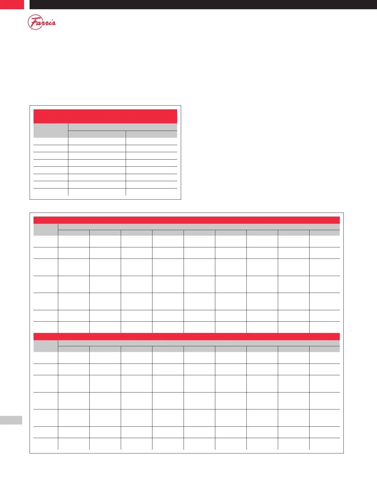
Maximum Seat Leakage Rates for
Metal-Seated Pressure Relief Valves
Set Pressure
psig
Leakage Rate (Bubbles per Minute)
F Orifice and Smaller G Orifice and Larger
15-1000 40 20
1500 60 30
2000 80 40
2500 100 50
3000 100 60
4000 100 80
5000 100 100
6000 100 100
Table 10.1
Table 10.2
Note 1: Use the second row only for “D” & “E” orifice valves purchased before July 1, 1993
Blow Down Ring Settings: Air, Gas, and Vapor Applications
Orifice
Set Pressure Range, psig
15 - 100 101 - 200 201 - 300 301 - 400 401 - 500 501 - 600 601 - 800 801 - 1000 1001 & Up
D
1
3
2
4
2
6
3
7
4
7
4
9
5
9
5
9
6
10
7
E
1
5
2
9
2
12
3
15
4
15
4
18
5
18
5
19
6
20
7
F
G
H
2
3
3
3
4
4
4
5
5
5
6
6
5
6
6
7
8
8
8
9
9
9
10
10
10
11
11
J
K
L
3
4
4
5
5
6
5
6
9
6
7
9
6
7
9
8
9
10
9
10
10
10
11
11
11
12
12
M
N
P
4
5
6
6
10
16
12
15
20
12
15
20
12
15
20
12
15
20
12
15
20
12
15
20
12
15
20
Q
R
6
4
16
16
20
20
20
20
20
–
20
–
20
–
20
–
–
–
T
U
4
4
16
16
20
20
–
–
–
–
–
–
–
–
–
–
–
–
Blow Down Ring Settings: Steam Applications
Orifice
Set Pressure Range, psig
15 - 100 101 - 200 201 - 300 301 - 400 401 - 500 501 - 600 601 - 800 801 - 1000 1001 & Up
D
1
3
2
4
3
6
4
7
5
7
6
9
7
9
8
9
9
10
10
E
1
5
2
3
2
12
4
15
5
15
6
18
7
18
8
19
9
20
10
F
G
H
2
3
3
4
5
5
5
6
6
6
7
7
7
8
8
8
9
9
9
10
10
10
11
11
12
13
13
J
K
L
3
4
4
6
6
7
6
7
7
7
8
8
8
9
9
9
10
10
10
11
11
11
12
12
13
14
14
M
N
P
4
4
4
7
7
7
7
7
7
8
8
8
9
9
11
10
10
10
11
11
11
12
12
12
14
14
14
Q
R
4
4
8
8
9
9
10
10
11
–
12
–
13
–
15
–
–
–
T
U
4
4
8
8
9
9
–
–
–
–
–
–
–
–
–
–
–
–