38
General Notes:
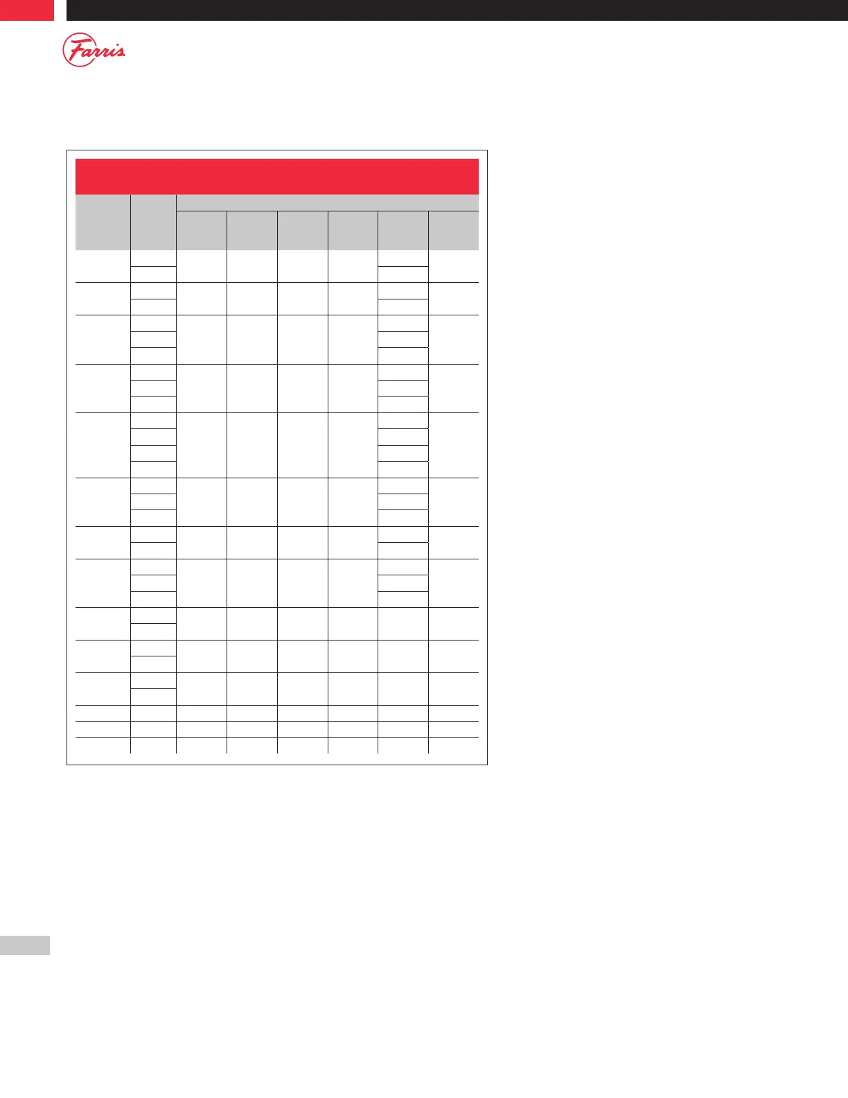
1. Z column designates flange class number to be inserted in type number, example: 26D( )( )3 would designate any of the “D” orifice 2600 designs
(conventional or bellows) with a 600# inlet flange.
2. Applies to valves with the A10 & A11 serial number suffix only. All others apply to both the A10 & A11 as well as the A14 & A15 Serial numbers.
3. For serial numbers suffixes; A10/H, A11/H, A14/H, A15/H, please consult factory for critical dimensions.
Table E.2: O-ring Seats - Serial Number Suffixes:
A10 & A11 / A14 & A15
Type Z
1
Nozzle Dimensions
B
+.000
-.005
C
+.000
-.002
D
min
F
min
L
min
Figure
26D( )( )z
0 - 3
0.520 0.615 0.078 0.01
4.141
4
4
2
4.375
26E( )( )z
0 - 3
0.585 0.800 – 0.01
4.081
5
4
2
4.375
26F( )( )z
3
0
0.720 0.880 0.078 0.01
4.219
42 - 3 4.344
4
2
4.344
26G( )( )z
0
0.885 1.052 – 0.01
4.063
52 - 3 4.203
4
2
4.203
26H( )( )z
0
1.110 1.255 0.078 0.01
4.906
4
2 4.125
3 5.000
4
2
5.000
26J( )( )z
0
1.416 1.568 0.094 0.01
4.094
42 - 3 5.156
4
2
6.531
26K( )( )z
0 - 3
1.730 1.937 0.094 0.01
6.516
4
4
2
7.891
26L( )( )z
0
2.106 2.312 0.094 0.01
6.438
42 - 3 7.563
4
2
7.563
26M( )( )z
0 - 3
2.366 2.566 0.094 0.01 7.531 4
4
2
26N( )( )z
0 - 3
2.598 2.824 0.094 0.01 7.531 4
4
2
26P( )( )z
0 - 3
3.080 3.317 0.094 0.01 7.516 4
4
2
26Q( )( )z 0 - 3 4.045 4.191 0.094 0.01 8.734 4
26R( )( )z 0 - 3 4.985 5.191 0.094 0.02 8.016 4
26T( )( )z 0 - 2 6.366 6.581 0.094 0.01 10.375 4