42
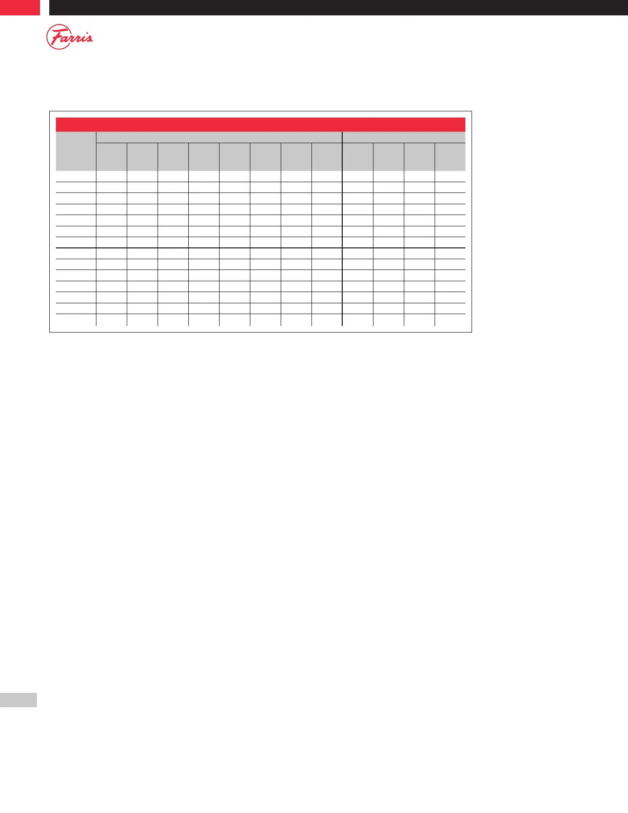
Table E.4: Metal Seats - Serial Number Suffixes: A10 & A11 Interim
Type
Nozzle Dimensions Disc Dimensions
A
+.010
-.000
B
+.000
-.005
C
+.005
-.000
D
min
E
+.005
-.005
F
min
L
min
Nozzle
Fig.
H
+.000
-.005
J
+.005
-.000
N
min.
Disc
Fig.
26D( )( )0 0.437 0.520 0.580 0.005 – .010 4.125 1 0.480 0.653* 0.156 1, 2
1
26D( )( )1 0.437 0.520 0.580 0.005 – .010 4.125 1 0.480 0.653* 0.156 1, 2
1
26D( )( )2 0.437 0.520 0.580 0.005 – .010 4.125 1 0.480 0.653* 0.156 1, 2
1
26D( )( )3 0.437 0.520 0.580 0.005 – .010 4.125 1 0.480 0.653* 0.156 1, 2
1
26D( )( )4 0.437 0.520 0.613 0.005 0.015 .010 4.375 2 0.480 – 0.156 2
26D( )( )5 0.437 0.520 0.613 0.005 0.015 .010 4.375 2 0.480 – 0.156 2
26D( )( )6 0.437 0.520 0.613 0.005 0.015 .010 4.375 2 0.480 – 0.156 2
26E( )( )0 0.535 0.585 0.645 0.005 – .010 4.062 1 0.545 0.725 0.234 1
26E( )( )1 0.535 0.585 0.645 0.005 – .010 4.062 1 0.545 0.725 0.234 1
26E( )( )2 0.535 0.585 0.645 0.005 – .010 4.062 1 0.545 0.725 0.234 1
26E( )( )3 0.535 0.585 0.645 0.005 – .010 4.062 1 0.545 0.725 0.234 1
26E( )( )4 0.535 0.585 0.685 0.005 0.015 .010 4.375 2 0.545 0.725 0.234 1
26E( )( )5 0.535 0.585 0.685 0.005 0.015 .010 4.375 2 0.545 0.725 0.234 1
26E( )( )6 0.535 0.585 0.685 0.005 0.015 .010 4.375 2 0.545 0.725 0.234 1
General Notes:
1. Only bellows valves use Disc Figure 2 and the 0.653 inch dimension. Conventional valves use Disc Figure 1.
These dimensions only apply to “D” and “E”
orifice valves as follows:
United States
A10 serial numbers below 30000.
A11 serial numbers below 4000.
Canada
A10 & A11 serial numbers C12001 and above.