6
Orifice
Letter
Area, Sq. In. Area, Sq. mm
API Actual API Actual
D 0.110 0.150 71 97
E 0.196 0.225 126 145
F 0.307 0.371 198 239
G 0.503 0.559 325 361
H 0.785 0.873 506 563
J 1.287 1.430 830 923
K 1.838 2.042 1186 1317
L 2.853 3.170 1841 2045
M 3.60 4.000 2323 2581
N 4.34 4.822 2800 3111
P 6.38 7.087 4116 4572
Q 11.05 12.27 7129 7916
R 16.0 17.78 10323 11471
T 26.0 28.94 16774 18671
U — 31.5 — 203.2*
V — 49.4 — 318.6*
W — 63.6 — 410.2*
W2 — 104.0 — 670.8*
X — 113.1 — 729.5*
Y — 143.1 — 923.0*
Z — 176.7 — 1139.7*
Type Numbering System
Our type numbering system simplifies the selection and specifying of Farris pressure relief valves because the digits that comprise a specific type number
have a distinct significance. The digits describe the basic valve series, orifice, seat and internal construction, inlet temperature range, body, bonnet and
spring material, inlet flange class and Code liquid design.
Inlet
Temperature
Range °F
Material
Body &
Bonnet
Spring
1 -20 to 800
Carbon
Steel
Chrome
Alloy
2** 451 to 800
Carbon
Steel
Chrome
Alloy
3 801 to 1000
Chrome
Moly
Steel
High Temp.
Alloy
4* 1001 to 1200 — —
5* 1201 to 1500
Austenitic
St. St.
Inconel
Alloy
1 -21 to -75 Use “S3” Trim Options
1 -76 to -450 Use “S4” Trim Options
6 -21 to -75
3-1/2%
Nickel
Steel
Carbon
Steel
7 -76 to -150
3-1/2%
Nickel
Steel
Austenitic
St. St.
8 -151 to -451
Austenitic
St. St.
Austenitic
St. St.
Designation
Prefix 26 D A 1
(if applicable)
Series Number Orifice Areas Construction Temperatures & Materials
H *
Set Pressure
Above API 526
SJ
Steam Jacket
HTF
Heat Transfer Fluid
* Available Only on
Q, R, T and U
Orifices
26
A
Conventional construction
B
BalanSeal construction
C
Conventional with
O-ring seat pressure seal
D
BalanSeal with O-ring seat
pressure seal
E
BalanSeal with auxiliary
balancing piston
F
BalanSeal with auxiliary
balancing piston and
O-ring seat pressure seal
T
Teflon seat, conventional
U
Teflon seat, BalanSeal
Note: Items listed in RED are for non-current nomenclature designations or options
no longer offered.
*The U – Z orifices are not API standard sizes.
U – Z metric areas = cm
2
.
This manual only covers maintenance for D – U
orifices. For larger orifices, please consult the factory.
* Temperature ranges 4 and 5 are beyond the scope of
this catalog. Consult the Factory.
** Temperature range 2 is no longer used as the standard
range valve handles temperatures to 800°F.
Figure 1.1 – BalanSeal Identification Plate
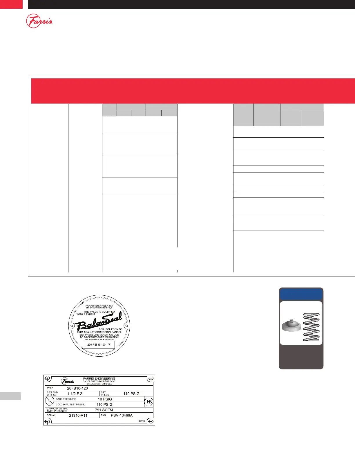
Figure 1.2 – Typical Farris Nameplate
Parts Replacement
Valves – If an exact replacement valve is
required, then the valve type, size and serial
number must be specified to ensure proper
dimensions and material being supplied. If a
specific valve is obsolete, a recommendation of
the current equivalent will be made if possible.
Spare Parts – When ordering parts, use part
names as listed in the bills of materials. Specify
valve type, size and serial number. If the serial
number is not available, the original Farris
factory order number will help us supply the
proper part and material.
Springs – Order as an assembly to include spring with upper and lower
spring buttons. Specify valve type, size, serial number, set pressure and
backpressure, if any.
Note: If valve modification or set pressure changes are required, consideration must be
given to correct the nameplate and other data.
OEM parts only!
NOTICE
Failure to use Farris OEM
parts can create dangerous
operating conditions, poor
valve performance and will
void the warranty.