MA5B
5 - MATCHING NETWORK
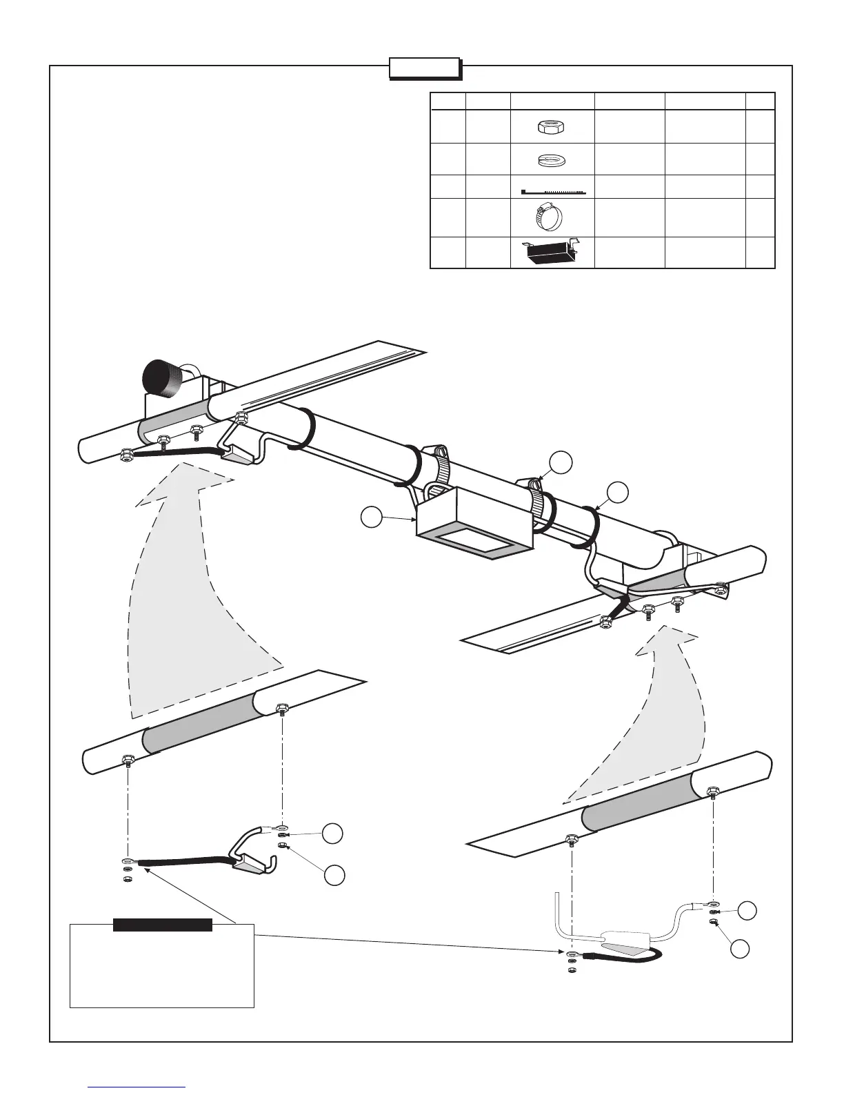
Install the matching network (MN) to the boom as shown in Figure 5.
Loosely attach the worm clamps (413) around the brackets on the
matching network and boom section. Attach the feed wires to elements
#1 and #2 as shown in the figure. Either cable may be attached to
either element, however, the polarity of the wires must be matched on
each element (i.e. the red wire on each element must be on the left
side and the black wire must be on the right side). Attach the wires
using lock washers (41) and hex nuts (11). Slide the matching network
to prevent over stressing the cables and tighten the worm clamps.
Attach cable ties (342) in 4 places around the cables and tighten.
2 PLACES
2 PLACES
11
41
2 PLACES
11
41
ELEMENT 1
ELEMENT 2
When attaching feedlines
to the elements, the black
wires must be attached
to the same sides.
IMPORTANT
2 PLACES
11 010011 HEX #8-32 4
NUT
41 011941 LOCK #8-32 4
WASHER
342 030342 CABLE TIE 4
413 030413 WORM CLAMP 1-3/4” 2
(4.4 cm)
MN MN5B MATCHING 1
NETWORK
KEY P/N DISPLAY DESC SIZE QTY
ELEMENT 1
ELEMENT 2
BOOM
413
342
2 PLACES
4 PLACES
MN
FIGURE 5
Page 9