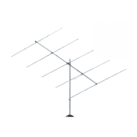
Assemble the elements per Figure 2. To assemble element #1, insert
the Fiberglass insulator (98) into element sections EA and align the
outer holes of the insulator with the holes in section EA. Place the 8-
32 machine screws (31) through the two holes and fasten with lock
washers (41) and hex nuts (11) as shown in Figure 2B. Place worm
clamps (411) over the ends of element EA and worm clamps (410) over
the ends of elements EB and EC. Insert elements EB into elements
EA to a 4-inch insert length. Tighten the worm clamps. Insert the MT1
traps into elements EB and EC, with the arrows pointing toward elements
EC. Adjust the total length of the assembly by using Chart A. Place
the plastic endcaps (61) over the ends of elements EC.
To assemble element #2, insert the Fiberglass insulator (98) into element
sections ED and align the outer holes of the insulator with the holes in
section ED. Place the 8-32 machine screws (31) through the two holes
and fasten with lock washers (41) and hex nuts (11). Place worm clamps
(411) over the ends of element ED. Place worm clamps (410) over the
ends of elements EB and EE. Insert elements EB into elements ED to
a 5-inch insert length. Tighten the worm clamps. Insert the MT2 traps
into elements EB and EE, with the arrows pointing toward elements
EE. Adjust the total length of the assembly to 205.5 inches (522 cm).
. Place the plastic endcaps (61) over the ends of elements EE.
To assemble element #3, place worm clamps (411) over the ends of
element EF. Place worm clamps (410) over the slotted ends of elements
EB and EC. Insert elements EB into elements EF to a 4-inch insert
length. Tighten the worm clamps. Insert the MT3 traps, with arrows
pointing toward elements EC, into the ends of elements EB. Tighten
the worm clamps. Place elements EC over the ends of the traps and
tighten the worm clamps. Adjust the total length of element #3 by using
Chart A. Place the plastic endcaps (61) over the ends of elements EC.
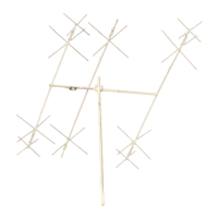
2 Element Assembly
11 010011 SS HEX NUT 8-32 4
31 010231 SS SCREW 8-32 x 1-3/4” 4
(2.9 x 91.4cm)
41 011941 SS LOCK 8-32 4
WASHER
61 050061 PLASTIC CAP 7/8" 6
(2.2cm)
96 122096 FIBERGLASS 1" x 10" 2
INSULATOR (2.5 x 25.4 cm)
410 030410 WORM CLAMP 1" 12
(2.5 cm)
411 030411 WORM CLAMP 1- 1/4" 6
(3.2 cm)
EA MA5BEA ALUMINUM 1-1/8" x 34” 2
TUBING (4.4cm)
EB MA5BEB ALUMINUM 1-7/8" x 36” 6
TUBING (4.8 x 91.4 cm)
EC MA5BEC ALUMINUM 7/8" x 7” 4
TUBING (2.2 x 17.8 cm)
ED MA5BED ALUMINUM 1-1/8" x 46” 2
TUBING (2.9 x 116.8 cm)
EE MA5BEE ALUMINUM 7/8" x 12” 2
TUBING (2.2 x 30.5 cm)
EF MA5BEF ALUMINUM 1-1/8" x 84” 1
TUBING (2.9 x 213.4 cm)
MT3 MT3 TRAP 24” (70 cm) 2
MT2 MT2 TRAP 17” (43.2 cm) 2
MT1 MT1 TRAP 24” (70 cm) 2
KEY P/N DISPLAY DESC SIZE QTY
MA5B
MT3
MT2
MT1
Page 4