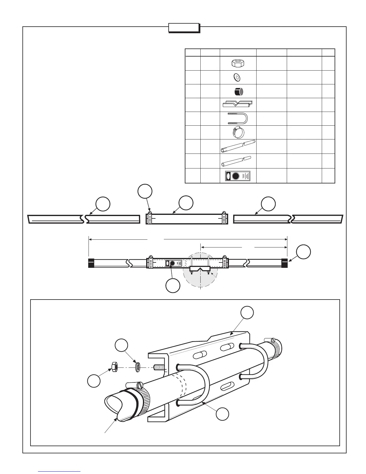
1 - BOOM ASSEMBLY
Place the worm clamps (413) over the slotted ends of tube BB. Slide
both BA sections into BB as shown in Figure 1. Each BA section
should be inserted 12 inches (30.5 cm) into section BB to leave 32
inches (81.3 cm) exposed on each end. Tighten the worm clamps.
Place the plastic caps (46) on the ends of the boom assembly.
Locate the boom to mast plate (70) at a distance of 36 inches (91.4
cm) from one end as shown in Figure 1. Bolt the plate to the boom
using the U-bolts (403), lock washers (19), and hex nuts (18). Apply
the danger label (326) to the boom near the mast plate.
KEY P/N DISPLAY DESC SIZE QTY
18 010118 SS Hex Nut 5/16-18 4
19 010119 SS Lock Washer 5/16 4
46 050046 Plastic Cap 1-1/2” (3.8 cm) 2
70 190070 Boom To Mast 6” x 3-1/2” 1
Plate (15.2 x 8.9 cm)
403 010403 U-Bolt 5/16” x 2” 2
(5.1 cm)
413 030413 Worm Clamp 1-3/4” 2
(4.4 cm)
BA MA5BBA Aluminum Tube 1-1/2” x 44” 2
(3.8 x 111.7 cm)
BB MA5BBB Aluminum Tube 1-5/8” x 24” 1
(4.1 x 61 cm)
326 290326 Warning Label 1
MA5B
46
2 PLACES
BA
BA
BB
413
2 PLACES
403
70
18
19
BOOM
4 PLACES
4 PLACES
FIGURE 1
FIGURE 1A
88”
36”
SEE FIGURE 1A (BELOW)
FOR BOOM TO PLATE ASSEMBLY
(223.5 cm)
(91.4 cm)
326
Page 3